Stanley MeyerHHO
#Hydrogen #Electric #Generator

Stanley Meyer's water fuel cell - Wikipedia, the free encyclopedia
HHO Motorcycle Alternator Rectifier Charging System Details
Secure Supplies has the parts you need please support make contact with us and advise your make model or parts need. We welcome builder to source parts from us. In thise Section we Detail Motor Bikes and all varients of ATV and Small Engines like Jet Ski etc. Stator Rectifier and boosters Products are are the Bottom.
Basically we are explaining that you need to improve the Alternator Stator and Rectifier to run HHO Hydrogen demand at fuel replacement levels.
We also recommened reducing electrical loads by considering to switch your light system over to leds ,
ever little bit of electric gain helps when adding HHO Cells to our Motor Bike electrical System Please Read on !.
Dan.
The Basics of a Motorcycle Charging System
On almost every motorcycle you will find a battery, used for providing power for starting the bike and for buffering an amount of electric energy. The battery itself is charged by a generator driven by the engine, and as long as the engine is running there will be a current flowing through thebattery. The no load voltage of a fully charged battery is about 13 Vdc. For charging it the charging-system should provide a voltage of about 14.4 Vdc and this should be a constant voltage at all engine-speeds.
The generator itself is located in or on the engine, and on most bikes there is a separate regulator-rectifier unit located somewhere on the frame. The reason for this is that almost all motorcycles are equipped with a three-phase AC (Alternating Current) generator, while the electrical system on the bike is a DC (Direct Current) system. The rectifier part inside the regulator-rectifier takes care of converting the AC-current to the DC-current the battery needs. The three-phase AC generator is used so often because it is much more efficient and reliable than a DC-generator. It can produce power for charging the battery even with the engine idling. The regulator part of the regulator-rectifier is used to regulate the output-voltage (to the battery) to the 14.4 Vdc that is needed.
The Permanent Magnet Generator System
A generator on a bike is producing this electrical power because it has a copper wire winding on the stator (the static part of the generator) that is located inside a varying magnetic field. The simplest generator uses a flywheel that runs on the crankshaft with a couple of magnets inside it. We call this flywheel with its built-in magnets the rotor.

FIGURE 1: PERMANENT MAGNET GENERATOR
The magnets themselves have north and south-poles and the flywheel is rotating around the stator. The stator is a metal core with a lot of metal poles that have windings of copper-wire on them. Because the flywheel is rotating and there are north and south-poles inside it, the windings of the stator are exposed to first a north-pole, then a south-pole, then a north-pole again etc. This is the varying magnetic field that is needed to let the winding itself produce AC-current. The windings themselves are connected in a star (one winding has two ends and the three ends of the three different windings are connected together) so the stator has only three output wires emerging from it.
This generator-setup we call a permanent magnet generator. This is because the flywheel contains magnets that are magnetic all the time. The output of a certain stator is depending on the engine-speed (the higher the speed of the magnetic-field variation, the higher the stator-output), and the force of the magnetic field (which is constant) Basically the stator produces a certain output at a certain rpm.
Then the AC-current is led through the rectifier inside the regulator-rectifier-unit. The rectifier converts the three AC-phases to a single 14.4 Vdc output, a ground and a positive. Because the stator is producing power according to the engine-speed the stator-output is too high all the time. This would mean the output voltage of the regulator-rectifier would be way over 14.4 Vdc all the time, which would result in an overcharged battery and blowing electrical components on the bike that were meant to run on a voltage between 12 and 15 Vdc.
Luckily there is also a regulator-part inside a regulator-rectifier. The regulator looks at the DC-voltage across the battery-terminals and short-circuits a certain amount of power that is produced by the stator to ground. This is regulated constantly, so the output-voltage of the regulator-rectifier (which ideallyis the same as the voltage across the battery-terminals) stays at 14.4 Vdc all the time.The permanent magnet generator-setup is not very efficient, but it is very simple and quite reliable. This explains why it is the most commonly used system on motorcycles.One of the problems with these systems is the short-circuiting of the excess power itself. This is done by the regulator-rectifier and this part has to dissipate the power that it shorts to ground, meaning it will get very hot. This is mostly because of the regulator and partly by the rectifier-diodes themselves that get hot just because of the current flowing through it. The regulator-rectifier internals need to be built so that the heat is transferred efficiently from the electronical components themselves to the housing of the unit, mostly equipped with cooling-fins. This is the most important bit in designing a regulator-rectifier for use in a permanent-magnet generator-setup.
The regulator-part of the regulator-rectifier needs to measure the DC-voltage somewhere in the system. On the cheapest built units (quite a lot of OEM ones) this is done not by measuring the DC-voltage in the DC-system, but by looking at the AC-voltage in between one stator-phase and the ground, and sometimes the excess power is shorted to ground from just one or two input-AC phases instead of all three phases that are regulated. The better built units measure the output-voltage of the unit itself and regulate the input AC accordingly by shorting more or less power to ground, an equal amount off all three phases.

FIGURE 2: PERMANENT MAGNET GENERATOR
Some units use an extra input wire (FIGURE 2) to measure the DC-voltage.This wire normally is connected up trough the ignition-switch and not straight to the battery.So there is only a voltage on this lead if the ignition is turned on. This is done to make up for a voltage-drop that can occur because of a bad-connection in the leads from the regulator-rectifier output to the battery-terminals. These leads carry a high current and any bad connection here will result in a lower voltage over the battery-terminals.
The extra lead carries a much lower current and the result of this setup is that the output-voltage of the regulator-rectifier will be higher, the same DC-voltage as the voltage-drop in the high current leads plus 14.4 Vdc. It has the advantage that the battery will charge, in spite of a bad connection, but has the disadvantage that the high-current leads can eventually burn out because of this, without the owner even noticing beforehand that there is a problem in the circuit.
One thing to keep in mind is that the output-power provided by the stator-winding is delivered in between the phases. The ground in the charging system is the negative output from the rectifier. The AC-part of the three phase system is floating from ground. This means that testing of the AC-output needs to be done IN BETWEEN two of the three phases, and not from one phase to ground.
The Field Controlled Generator System
The other system used on motorcycles is the field-controlled generator. The system itself works on the principles as a permanent magnet generator, the only big difference is that there are no permanent magnets but instead there is an electromagnet that provides the necessary magnetism. (This magnetism is normally called the "field") The electromagnet is a single big winding on a metal core that gets magnetized as soon as there is DC-current flowing through the winding, supplied by the battery. A car-generator basically uses the same system.
On most of the field-controlled systems this metal core has claw-poles and two slip rings. The whole thing rotates with the crankshaft, with the statorwinding (just like the permanent-magnet stator) around it. Imagine looking at the outer side of the rotor sideways. You will see two pieces of metal pressed together with a winding in between. When you apply battery-voltage across the sliprings, the rotor will behave like a big electromagnet, and the left-hand side of the rotor will be say a north-pole, then the right-hand side will be a south-pole. In the middle you can see the pieces overlapping, meaning when the rotor rotates there first will be a south-pole passing, then a north-pole, then a south-pole etc. This is the needed varying magnetic field for generating AC-current in the stator-winding. The three-phase AC output from the stator-winding is led through a rectifier (inside the regulator-rectifier-unit) to convert it to DC for charging the battery.

FIGURE 3: SWITCHED FIELD
Regulation is done by the regulator-part of the regulator-rectifier. It senses the voltage in the bike’selectrical system and when the voltage is lower than 14.4 Vdc it switches on the field (it switches a 12Vdc supply across the sliprings) Then there is a magnetic field, so the stator will produce power. When the voltage in the bike’s system reaches over 14.4 Vdc the regulator senses that and just switches the field off.Then the voltage will drop because the stator doesn’t produce any power anymore (there is no varying magnetic field). When the voltage drops below app14.2 V, the regulator switches the field back on.
This is a constant process and the result of this is a constant voltage across the battery-terminals of 14.4 Vdc. Because there is no excess power produced by the stator, this system is very efficient. Counterside is that it is not as simple and small as a permanent magnet generator. The field winding normally has one side connected to the battery-positive through the ignition-switch. So there is only power for the field when the ignition is turned on. Regulation is done through the regulator-part of the regulator-rectifier by switching the ground for the field on or off. On some machines the set-up is the other way around, then one side of the field is connected to ground at all times, and the other side is switched on or off to a positive feed (through the ignition-switch) by the regulator.
The Maintenance Free Field Controlled Generator
Some machines have a slightly different setup. Then the stator is located inside a cover, as well as the field winding in the middle of it. In between rotates an iron claw-pole driven by the engine. The claw-pole gets magnetized by the field winding and the system works like the field-controlled one as explained above. The difference is that the field does not rotate, so it doesn’t need to be powered through slip-rings and brushes, which makes it virtually maintenance-free. Counterside of this setup is the extra airgap between the fieldwinding and the claw-pole. Normally you have a very narrow airgap between rotor and stator that is needed to let the rotor rotate freely. This airgap needs to be as small as possible, the smaller the airgap, the more efficient the generator works. On this maintenance free system there is an extra airgap, so this system is less efficient.
The Unit Field Controlled Generator
The last variant of this system is a car-type generator that is bolted onto the bike's engine as a single unit. It is driven by the engine itself and has a built-in rectifier, and a built-in regulator, just like a car-generator.The only connections to it are the positive output-lead to the battery-plus and a supply-lead from the ignition-switch to the regulator inside, so the regulator can be turned on and off when the engine is not running, and it can sense the voltage on the bikes electrical system on this wire. Sometimes there is a third wire coming from it, which is a ground-lead, to the frame or the battery-negative. So because the rectifier and the regulator are built into the generator itself, there is only DC-voltage (14.4 Vdc) coming from this generator.
Pulser Coil & Ignition Systems
The Pulser Coil is the heart of your engines timing & ignition system.
This section has information on how the components and system work & troubleshooting tips.
The Pulser Coil, (often called Pickup Coil, or Timing Coil) is responsible for providing the timing signal to the ignition control box on modern motorcycles with solid-state ignition systems. The majority of motorcycles from the late 1970's and up use this system for reliable, accurate, and low maintenance ignition control. On previous models, points-controlled systems were used, and while cheap and simple, they required routine maintenance and component replacement to ensure reliability.
Points & Mechanical Advance Ignition Systems
On most motorcycles up until the late 1970's, timing and spark control was done with a set of cam-driven points, which were mechanically advanced or retarded to control timing. The points would make contact, allowing current to build up. When the points were opened, and contact broken, the current was discharged through a coil to step up the output to high voltage in order to produce an ideal spark across the spark plug. This system was very simple, and similar to the system used on automobiles. The common replacement parts are the points, which wear down from constant friction as they open and close, and the condenser, which is a small capacitor to prevent arcing and premature wear & failure of the points. Timing is handled via a mechanical advance system. The timing of the points openening is advanced before Top-Dead-Center of the engine at higher RPM's, usually by means of a spinning weight.
CDI (Capacitor Discharge Ignition) & Solid State Ignition Systems


Modern ignition systems use a solid state (semiconductor) controller to handle the ignition spark timing. The control box, often called a CDI box, or black box, handles multiple functions. The internal electronics are either powered from the battery (DC ignition systems, most street motorcycles), or in AC directly from the stator (most dirt/offroad motorcycles). Current from either the stator or the battery is used to charge up an internal capacitor. This capacitor is then discharged through the ignition coil via the spark plug to generate the very high voltage necessary for a good spark. The CDI box has digitally stored timing maps, to handle advance of the ignition depending on RPM, and sometimes other variables, such as a throttle position sensor (often called TPS, a sensor which varies it's resistance based on the opening of the throttle). The CDI box is fed timing data from the Pulser Coil, which produces a short duration, low current, high voltage pulse in relation to the Top Dead Center (TDC) piston location in the engine. This is explained more in depth below.
The Pulser Coil and Flywheel Timing System
The pulser coil is a very simple component. It is generally housed in a small plastic container, and internally potted with epoxy or some other oil resistant material. The pulser coil itself is made up of a small magnet (the exposed metal you can see on the front of the housing), which is wound with a coil of very fine wire. The pulser coil may have one or two wires exiting the case to connect to the ignition box. On one wire systems, on side of the internal coil is grounded to chassis ground through the mounting hardware. On two wire systems, a wire from each side of the coil exits the case to connect to the ignition box.
The pulser coil generates it's timing pulse with help from the flywheel (Refer to the illustration above). The outside diameter of the flywheel has at least one timing mark, which consists of a raised ridge, spanning some percentage of the outer edge of the flywheel. This ridge is pronounced, and has sharp leading and trailing edges. The Pulser Coil is mounted to the engine sidecase in very close proximity (some thousands of an inch) to the flywheel, spaced to be extremely close to the timing ridge(s). The timing ridge is referenced to the Top-Dead-Center (TDC) piston location inside the engine. As the timing ridge on the flywheel spins past the pulser coil, the timing signal is generated. The leading and trailing edges of the raised metal ridge produce a low current, high voltage pulse, either positive then negative polarity, or negative then positive, depending on the direction of the coil winding inside the pulser coil. The ignition box then uses this signal to reference the piston location, and given it's inputs (RPM and TPS) it will determine the correct time to fire the spark plug, by discharging the internal capacitor out to the ignition coil, and finally the spark plug.
General Pulser Coil Troubleshooting Steps
The Pulser Coil, as a unit, is not usually serviceable. It is a sealed component, and should be replaced if determined to be a problem. Pulser Coil problems sometimes manifest themselves in hard starting situations, but usually failures result in no spark at all. When the pulser coil fails it will usually produce no output pulse, or a very weak one. This is hard to verify, without special tools such as an oscilloscope to view the pulse. The usual failure is similar to a stator failure mode, the wire coil inside fail with the insulation breaks down and a short occurring, or the wire breaks inside causing an open circuit. The wiring external to the pulser coil assembly can be damaged as well, causing a connection issue. The only real troubleshooting method is to check the resistance of the Pulser Coil wires, to ensure they match known specifications, making it likely the coil inside is intact.
1: Lookup Pulser Coil technical specifications for coil resistance. These are available from the bike's service or owners manual, or our website's product page for our coils.
2: Obtain a Digital MultiMeter (DMM). Set to the hundreds resistance range if the meter is not auto-ranging.
3: Attach each meter lead to one wire from the pulser coil. If there is only one wire exiting the pulser coil, attach one meter lead the wire, and one to the metal mounting foot of the pulser coil housing.
4: Verify resistance reading matches the known specification. For most Pulser Coils this in the range of 180ohms-300ohms, but please compare to exact specifications for your part.
5: If either an short is detected (no resistance), or an open (OL - overload, on most meters), the coil is definitely bad.
6: There are no serviceable parts in a pulser coil, short of repairing a damaged section of the wiring harness. Please replace with a new coil.
HHO Motor Bike Custom Stator Rewinding / Research & Development / Testing Services
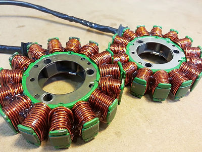
HHO Hydrogen On Demand Stator Repair / Stator Rewinding / Custom Stator Winds
Secure Supplies offers professional high quality stator winding services.
Our stator rewinds are done by hand by HHO Hydrogen On demand professional technicians using the highest quality high temperature rated magnet wire and durable insulating epoxy.
We ship Globally.
We can repair burned up and failed stators with a stock-specification rewind to get your bike on the road. We also can rewind your stators for higher output to whatever power level is necessary for your application.
High output custom stator winds are our specialty. We also offer custom stator winds using OEM cores for your application, from race use to prototype machine testing. Just let us know what you're looking for and what your needs are.
Stator winding service prices are always subject to a quote and review for your specific bike/project.
General pricing:
-
Stock rewind/repair (requires useable OEM core): $250
-
High Output Upgrade rewind (requires useable OEM core): $350
-
Special/Custom Application Engineered rewind (may require OEM core): $450-550+, depends on application
To get a quote on Rewind Services, please call or email!
+66 83 647 3443

Testing Services
RaceTech Electric offers in-house testing services for stators, voltage regulators, and other motorcycle electrical components. Stator & Voltage regulator testing is done in our R&D lab with custom built test equipment. Testing services can be arranged easily with a phone call. We offer discounted electronics testing services for local shops, and free for dealers. Testing services are $20 per item, all of which will be refunded upon purchase of a replacement stator or regulator from us. We can easily tell you if your stator is in good shape and producing all of it's potential power. We can heat cycle stators, and detect issues occuring only under high temperature or high load situations, which may be very difficult to detect on the bike. We can also stress test voltage regulators-regulator/rectifiers, cycling them through phases of high loading to full regulation. We can also check the voltage regulation point accurately, and detect rectifier diodes that are worn and on the verge of failure.
To arrange testing service, give us a call or email!
+ 6683 647 3443
Our motorcycle charging system tester allows for mounting of all permanent magnet flywheels, and drive speeds of up to 16,000 RPM to produce maximum power output in stators from all types of motorcycles.
The flywheel is mounted to a self-centering base, the spindle of which is belt driven by a large 3hp 3-phase electric motor. By using a very accurate Pulse Width Modulated motor controller, we are able to accurately drive the flywheel at a specific RPM.
Stators are mounted to a fixed base, with CAD-designed adapters to center different sizes of stator cores. The stator mount slides on tracks to enter the stator inside of the flywheel.
The stator can be tested using on-board equipment to simulate the rest of a motorcycles' charging system, or used to drive a regulator/rectifier unit. The on-board electronics include 2 large high-Farad capacitors, a three phase bridge rectifier, and a large 500W switchable resistive load bank.
The paralleled capacitors simulate a dead motorcycle battery, that needs to be charge as the stator begins producing current. The bridge rectifier allows DC testing without needing a separate regulator/rectifier unit.
The load bank can switch in up to 500W of resistance in units of 10/20/50/100 Watts, to simulate the load on the battery & charging system (think lights, electrical accessories, heated grips, HHO Cell PWM etc.).
Voltage Regulators
The Voltage Regulator is an important component of the electrical charging system, and keeps your motorcycle battery from being overcharged and damaged. This section has information on common regulator types and troubleshooting information. There are a few common types of Voltage Regulators used on most motorcycles. The most common is a single or three phase regulator for permanent magnet charging systems. This type is used on the majority of modern street motorcycles. A different style of regulator is used on field coil regulated systems, which are found on many street motorcycles from the 1970's through early 1980's. And finally a very simple regulator is used on alternator type systems. Most Voltage Regulators contain a Rectifier component as well, and they are often referred to as 'Regulator-Rectifiers'. The Rectifier is a separate, but equally important component, which serves to convert ("rectify") the alternating current (AC) produced by the stator & flywheel to direct current (DC) necessary to charge a battery. The different types are explained in more detail below.
Permanent Magnet Flywheel Voltage Regulators
Single Phase Voltage Regulators

Single Phase Voltage Regulators are used with single phase stators in permanent magnet flywheel charging systems. You can see the stators and rotors pages to learn more about these type of systems. The Single Phase Voltage Regulator serves two functions. First, is to act as a Rectifier (why these are often called Regulator-Rectifer's). The rectifier section is represented by the 4 arrows in the schematic above. The arrows represent the internal Diodes, which are electronic components inside unit which form the Rectifier section. Diodes are a simple electrical component that serve a single function. Diodes can be though of as one-way streets for electrical current. They only allow current to pass in one direction: positive polarity. The single phase rectifier has each end of the stator coil connected in between a pair of diodes. The diodes filter out the negative portion of the alternating current wave, only allowing the positive polarity current to pass. After the diode bridge, the electrical current from the stator is rectified into direct current, which is used to charge the battery.
The Regulator is separate set of components and function inside the unit. The regulator function is very simple (and reliable) in most motorcycle regulators. A regulator control circuit monitors battery voltage, and compares this measurement to an internal reference voltage (the regulation point). Motorcycle regulators are generally designed to allow a maximum battery voltage of ~14.6VDC at the battery while charging. When this voltage limit is reached, the control circuit triggers semiconductor switches, called 'Silicon Controlled Rectifiers' (SCR's). When the SCR is triggered, it essentially closes a switch, making a connection between the output of the stator, and ground. This act shunts stator output to the ground, which is dissipated as heat throughout the regulators body. This is why the regulator housing design is critical. It not only serves to protect the internal components from the elements & vibration, but neds to efficiently dissipate heat as excess current is bled off. Fins are often used to allow airflow to help cool the housing.
Three Phase Voltage Regulators

Three Phase voltage regulator/rectifiers function the same way as described above in the single phase section. The differences are the rectifier brige contains another set of diodes to rectify the third phase of output from the stator.
Field Coil Rotor Regulators

These Voltage Regulator units are of the type used on bikes that use a rotor with an internal field coil, instead of a permanent magnet flywheel. This type of system is used on many Japanese motorcycles throughout the 70's and early 80's, like the Honda CB series & Yamaha XS series. These units have an internal rectifier, that functions the same way as the units described above. The difference with this type of system is in the regulation. Regulation in these systems is done by varying the current flow through a field coil inside of the rotor to vary the magnetic field, rather than shunting stator output (see permanent magnet systems above). The regulator senses battery voltage, and regulates current flow to the field coil. When the battery voltage is low, the regulator allows maximum current to flow through the field coil, increasing the magnetic field in the rotor. This, in turn, increases the output from the stator windings. When the measured battery voltage reaches full charge (~14.4V), current flow through the field coil is reduced, or stopped altogether (depending on the particular model), to avoid overcharging the battery. These systems are more efficient than Permanent Magnet charging systems, as there is not as much wasted current being generated that has to be dissipated as heat. However there are more parts to wear out in these systems, such as the slip rings on the rotor, or the brushes providing current to the field coil.
Alternator Regulation
Some motorcycles, particularly street models in the 80's, used an automotive-type alternator system. In these units an alternator is usually gear driven from the crankshaft. The alternator has an internal diode bridge to perform AC->DC rectification (see description above). The alternator has an internal field coil, which is controlled by a separate regulator unit (also internal to the alternator). The regulators can fail on these units, and are easy to replace.
General Voltage Regulator (Regulator/Rectifier) Troubleshooting Steps
Voltage Regulator units generally fail from heat. Most regulators work to protect the battery by dissipating unnecessary charging current as heat. The heat is sunk by the metal body of the regulator. On most bikes, the regulator body is finned for air-cooling, and is mounted in some location with decent airflow. If a regulator fails often on a particular model, and the regulator is mounted in a location with poor airflow (underneath the seat, under a fairing, near exhaust, etc.) it can help to move and re-mount the regulator housing somewhere on the bike with very good airflow.
Regulation Failures
The regulation functions of a Voltage Regulator unit cannot be easily tested. (We offer testing services on our test bench, where we can accurately diagnose a regulator failure. Please contact us to arrange testing services.) Regulation failures will generally present themselves by over-charging the battery. This may be noticeable by blowing up headlight or taillight bulbs from high voltage, or the battery getting extremely hot, and boiling the acid inside. This can be easily diagnosed with a Digital MultiMeter (DMM).
1: Connect your DMM to the battery terminals, Red DMM lead to the Positive (+) terminal, Black DMM lead to the Negative (-) terminal.2: Set the DMM to DC Voltage mode, 20V range.3: Start the engine.4: Note battery voltage at idle. It should be in the range of 12V - 13VDC at idle.5: Rev the engine to 4000-5000RPM, and check the DMM reading.6: The regulator should reach ~14.4 - 14.6VDC.If the voltage continues increasing with RPM over 15VDC, the regulation function is not operating correctly. The regulation function is not serviceable at all, the Voltage Regulator must be replaced. Regulation functions can be intermittent, and get progressively worse. It can be hard to test and be positive of regulator failure, but this is the easiest and most common way to diagnose this failure. Rectifier Failures
The rectifier function can be easily tested, by checking for correct operation of the diodes in the internal rectifier bridge. You do need a Digital Multimeter with a Diode Check function. This will be a symbol on the meter looking like an arrow (-->|--). The diode test function operates by sending a small supply of DC current from the meter's internal battery out through the meter leads. To perform this test, you will connect the meter leads in both directions across each diode inside the Voltage Regulator. When the leads are connected in Positive Polarity position, the diode should allow current to flow, and the meter will display the voltage drop across the diode (usually 0.5 - 0.7 VDC). When the leads are connected in Negative Polarity position, the diode should not allow any current to flow. In this case a DMM will generally display 'OL' for OverLoad, or no connection/no voltage drop. To perform this test:
Note: The wire colors in the tests below are for the majority of motorcycles. If the color is the not the same on your regulator, try and trace the wires to determine their function.Yellow wires are the two or three wires that connect to the stator. These are white on some bikes.Red wire is the Positive DC output from the regulator to the battery. On some bikes this is White/Red.Black wire is the Negative DC output (Ground) from the regulator to the battery. On some bikes this is Black/White, Black/Yellow, or Green.Forward Bias Diodes*Connect the BLACK Digital MultiMeter (DMM from now on) Lead to the Red wire in the Regulator/Rectifier's (RR from now on) connector.*Connect the RED DMM Lead to one of the Yellow wires in the RR connector.=The DMM should read from 0.400 - 0.600 VDC, and most meters will beep, if the diode is functioning correctly in the forward bias mode.*Continue this same procedure with the other Yellow wires in the RR connector, noting if any fail.*A diode is bad if the meter displays 0.000, has a continuous beep, OR the meter displays any number other than 0.400 - 0.600 VDC, OR the meter displays 'OL'.Any of these results mean the diode has failed by being internally shorted (it will not block current in other direction), is internally open and not passing current at all, or is starting to fail in one of these ways.Reverse Bias Diodes*Connect the RED DMM Lead to the Red wire in the RR connector.*Connect the BLACK DMM Lead to one of the Yellow wires in the RR connector.=The DMM should display 'OL', if the diode is functioning correctly in the reverse bias mode.*Continue this same procedure with the other Yellow wires in the RR connector, noting if any fail.*A diode is bad if the meter displays 0.000, OR the meter displays ANY number value at all.Any of these results mean the diode has failed by being internally shorted (it is flowing current in the reverse direction, which it should block), is internally open and not passing current at all, or is starting to fail in one of these ways.
If you note one or more diode failures in the Rectifier testing steps above, the Voltage Regulator unit must be replaced. There is no internally serviceable parts inside.
Stators
The motorcycle engine Stator is the heart of the electrical system, providing electrical current for your engine for battery charging, lighting, and the ignition system. This section has descriptions of the common types, and troubleshooting information.
There are a few types of stators commonly used on motorcycle and powersports engines. This document will have descriptions of the main types, with troubleshooting information at the bottom. There have been some improvements and changes over the years, but the common basic motorcycle stator has been the same since the 1970's.
Permanent Magnet Flywheel System

Permanent magnet flywheel systems are the most common, and simplest form of generating power for a motorcycle electrical system. The permanent magnet flywheel consists of a cupped metal flywheel that mounts to one end of the crankshaft in the engine. The crankshaft end and the inside of the flywheel share a taper, that allow for a tight, high-friction fit. The flywheel is then secured to the crankshaft with a nut or bolt (depending on internal or external threads). This is usually on the riders left side of the engine (most common Japanese models), and spins consistent with engine RPM. The flywheel has timing notches on it's outer diameter that work with the pulser coil (see pulser coil section for timing and ignition system information). The timing notches on the flywheel are keyed to Top Dead Center location of the pistons by means of a slot in flywheel taper, and a key (called a 'Woodruff key') pressed into the crankshaft end.
The flywheel is constructed with internal magnets along the walls. The magnets are alternating North & South (Positive & Negative) polarity magnets. These magnets are spaced according to the poles (arms) of the stator. As the flywheel rotates on the crankshaft, alternating positive & negative polarity magnets cross poles for the same coil of wire (wound in opposing directions). This magnetic field crossing in close proximity to the stator coils produces an alternating current in the stator windings. The positive side of this system is it's simplicity and reliability. The negatives are excessive heat buildup in the stator windings, as the magnetism is constant, and the stator produces maximum possible current at all times; the only variable being engine RPM.
DC Ignition System
DC ignition systems are common on modern sport & street motorcycles. This type of system means the entire output of the stator is current intended for charging the motorcycle's battery. The stator is wound in either a single or three phase configuration with large diameter wire, to produce relatively high current and low voltage. It is configured to produce as much current as possible across the entire RPM range of the engine. The ignition system is powered off of the battery, which is capable of providing a very powerful spark. This also means it is critical for the motorcycle to have a fully charged battery, and the bike will not run with a discharged battery.
Single Phase Charging Stator

Single phase charging stators consist of a single coil wound among all the poles of the stator. The coil alternates winding direction on each pole. Some stators will have one end of the coil grounded by attaching to the stator core. This simplifies the wiring harness, as only one wire needs to be attached to the bike's wiring, as the other end of the coil shares a chassis ground with DC side of the system. However other stators have the coil 'floated', and have 2 wires, for both sides of the coil, exiting the stator core. Single phase charging stators are simple and reliable, but produce less current and are much more dependent on RPM than the three phase alternatives.
Three Phase Charging Stator

Three phase charging stators consist of three separate coils wound alternating every third pole of the stator. Each coil alternates winding direction on each pole. There are two variations of three phase stators, called Wye, and Delta configurations. These describe the way the three coils are connected to each other. It is out of the scope of this overview to go into too much detail on each configuration, but both types are commonly used in three phase motorcycle stators, depending on the engine design and charging needs. A Delta configuration has one end of each coil connected to another in series, looking like a Delta symbol (triangle) when drawn. A Wye configuration shares one end of each coil connected together in a common spot, and the opposite end of each coil being the output. This looks like a Y when drawn. Delta connected stators generally produce a higher current flow at RPM's, and are ideal for many three phase battery charging stators. Wye connected stators are capable of producing higher voltage at lower RPM's. Three phase stators overall are much more efficient than their single phase counterparts. They produce more current at lower RPM's, and overall much more across the entire RPM range than a comparable single phase stator, making them ideal for most street motorcycles (and many larger dirt motorcycles with batteries).
AC Ignition System
AC ignition systems are common on dirt/off-road motorcycles, where reliability & weight is of the utmost importance. An AC ignition system does not require a battery, rather powering the ignition system directly from the stator. These systems operate with a permanent magnet flywheel like the description above. The stators are generally very small, often with a single a coil providing a single phase alternating current output to power the ignition system. These systems are very reliable, as the bike always be kickstarted or push-started easily, without having to worry about whether a battery is charged to power the ignition system. They are also used on motocross and racing model since a battery is not required, and weight is kept to a minimum by eliminating a heavy battery and regulator-rectifier unit.
Ignition Only

AC ignition only systems are the simplest form. They are commonly used in motocross and racing models since they do not require a battery or other components. The stators are physically small, and very light. They can include single, or multiple coils (always single phase output) that power the ignition system directly. The coils are generally wound with many turns of extremely fine (small gauge) wire, to produce very high voltage and low current output.
Ignition with Single Phase Charging

These systems operate the ignition system as described above in the Ignition Only section, but are generally slightly larger stators. They include a single phase charging coil wound on the majority of the stator poles. This coil is used in conjunction with a single-phase regulator-rectifier unit to charge a small battery. They are often seen on enduro type off-road bikes (example: Yamaha WR models) with an electric starter and/or lighting system that are powered from the battery.
Ignition with Three Phase Charging

These systems operate the ignition system as described above in the Ignition Only section, but are generally full size stators. They include at least one single phase coil to power the ignition system. They also have a three phase charging output wound on the majority of the stator poles. This output provides a great deal of current to charge a larger battery. These systems are often used street-legal off-road or dual-sport bikes that require a full lighting system with headlight, taillight, turn signals, horn, etc. for street registration requirements. The ignition is still powered directly off the stator for off-road reliability (a fully charged battery is not required to run the ignition system). Another feature of this system is being able to power the lighting system from the battery while the engine is off, which is generally a requirement for street legal motorcycles. A good example of this system is Suzuki DR-Z400 models.
General Stator Failure Information
Stators fail in multiple ways, but are generally simple to troubleshoot. A stator almost always fails due to heat buildup causing an insulation failure of the wire. Keep in mind that a stator is composed of hundreds of feet of very fine wire, with very thin insulation, wound at relatively high tension around a metal core. The stator lives a high stress life, always surrounded by heat. The stator itself produces heat, as it is a by-product of current generation as the magnetic flywheel spins around it. On most engines (specifically 4-stroke's) the stator lives in a bath of oil from the crankcase. While this oil does provide cooling functions as the stator is immersed in it, the ambient temperature is very high as the oil is heated by engine operation. The stator generally fails from a hot-spot of the wire's insulation wearing through, resulting in two types of short-circuit failures. If the insulation fails somewhere in the middle of a winding, a short circuit occurs in the coil. The remaining wire in the coil after the short is no longer in the circuit, and the winding's output drops by the percentage of the coil that is bypasses. On a charging coil, this is often not immediately apparent, as the stator may still produce enough current to keep the battery marginally charged for a time, but it will start to be noticeable as the battery is never fully charged. The short will often get worse, or occur at other locations on the winding, continually reducing the output. Taking a resistance reading of the coil (described below) and comparing it to the technical resistance specifications of the stator windings (available on all of our product description pages) will help you troubleshoot this type of failure. The other common type of short-circuit failure on a stator is a short to the stator core, engine case, or commonly called 'ground'. This type of failure occurs when a wire's insulation melts, or is worn through, and allows the wire strand to touch the stator core. The stator core is grounded to the motorcycle chassis through it's mounting bolts. This type of short generally completely destroys the stator coil's output, resulting in no charging or ignition current output. It will often be noticeable as a dead battery, or no spark produced by the ignition system. Keep in mind that the wires exiting the stator to attach to the bikes wiring harness can also have the insulation nicked, or melted, and cause the same kind of failures outside of the windings on the stator poles.
General Stator Troubleshooting Steps
A Digital MultiMeter (DMM) is the most important tool for troubleshooting a motorcycles electrical system. We recommend a reasonably priced, but high quality Fluke model. Lots of different makes and models are available on Amazon.com, and many other online retailers. To detect either of common stator failure modes described above, a simple resistance check is all that is required.Coil Resistance Check:Turn on DMM.Set DMM to resistance (ohms setting), set to lowest range.Attach DMM leads to each pair of wires for each stator coil.Compare resistance measurements to technical data (available in OEM shop manual, or our product description pages).If resistance matches reading, coil is most likely fine.If DMM shows 'OL' (overload) or infinite resistance, coil could be broken, wire not internally connected.If DMM shows 0ohms or continuity (dead short), a short could exist between output wires of stator or in the connector.Coil Short to Ground Check:Turn on DMM.Set DMM to resistance (ohms setting), set to lowest range.Attach one DMM lead to a good chassis ground point (or negative terminal of battery).Attach one DMM lead to each output wire from stator, in turn.On most models and wires, correct measurement should be 'OL' (overload), or infinite resistance.If resistance is measured, or no resistance (dead short), stator winding is internally shorted at some point to stator core or chassis.In either case, stator most likely needs to be replaced. These descriptions and troubleshooting tips should give you a starting place to understand your motorcycle stator, and electrical system. We are always available to help with troubleshooting, and would be happy to help you diagnose your problem before ordering from us. We want to make sure you get the right part you need, not spend money unnecessarily on electrical components that are not bad.
Rotors
Field Coil Rotors provide the magnetism to drive charging system output in many bikes. These systems were used on many bikes in the 70's and 80's. Good examples include the Honda CB series, and Yamaha XS series motorcycles.
They function more similarly to car-type alternators than the permanent magnet flywheel systems described on the stator tech support page. They are more efficient systems in that they vary the magnetic field of the rotor to only generate as much charging current as needed by the battery at a given time.

Field coil rotors are an efficient way to generate the magnetic field for a motorcycle charging system. The rotor is made from two metal halves, pressed together. Inside the rotor is a plastic insulating core wound with magnet wire. The face of the rotor is a flat surface, with two isolated copper rings (called 'slip rings'). Each ring is internally connected to one end of the field coil. The field coil is powered by +12VDC provided by the voltage regulator.
The current is passed to the rotor via brushes that ride against the slip rings as the rotor rotates. The rotor is mounted to the end of the engine's crankshaft, and rotates at engine RPM. The rotor is surrounded by an external stator with windings in close proximity to the edge of the rotor. The field coil rotor is controlled by the voltage regulator in the system. The voltage regulator/rectifier in a field coil rotor system serves multiple functions. It measures battery voltage, and based on the level of battery charge allows varying amounts of current flow through the field coil. The current through the field coil then generates a magnetic field, which produces alternating current flow through the windings of the stator that surrounds the rotor. The rectifier side of the voltage regulator/rectifier then rectifies the alternating current from the stator to DC current to charge the battery.
General Rotor Failures
Rotors cannot be easily serviced or repaired, although if the field coil fails, it is possible to separate the rotor halves and rewind the field coil. There are only a few common failure modes of field coil type rotors. Most common is the field coil failing due to wire insulation wear. A bad spot on the field coil winding insulation will eventually develop, and short the field coil internally, either between windings, or to the body of rotor. The entire length of wire in the coil is necessary to generate a sufficient magnetic field, so any loss of winding due to short circuiting will cause a large drop or complete failure in charging output.The other common failure mode of rotors is slip ring wear. As the brushes are constantly sliding on the slip rings and passing electrical current, the rings can eventually corrode, and the copper surface wears down and becomes uneven. This can cause a poor connection between the brushes and rings, resulting in high resistance in this connection, and poor current flow to the field coil. The surface wear can damage the brushes as well. The face of the rotor needs to be clean and even to ensure reliable operation.
General Rotor Troubleshooting Information
A Digital MultiMeter (DMM) is required to complete testing of the field coil.Field Coil Resistance TestSet DMM to resistance measurement mode (ohms) at lowest range.Use meter leads to measure resistance between the two copper slip rings on top of the rotor.Compare readings to the technical specifications of the part (available on the part description page for our parts, or OEM Shop Manual). If the reading does not match the target resistance, the field coil is suspect.Much higher resistance can mean damaged windings.
Field Coil Short Circuit TestSet DMM to resistance measurement mode (ohms) at lowest range.Use meter leads to measure resistance between each ring on the face of the rotor and the metal body of the rotor.This measurement should display infinite resistance ('OL', overload on some meters), indicating the field coil is completely isolated from chassis ground.If there is any measurable resistance (especially low) or a short circuit in these measurements, this indicates the field coil is internally shorted to the rotor housing at some point, and will not operate correctly, if at all.
At Thread conversation which can help, Clipped from a Advanced Forum
I have a KTM 250 enduro bike that has a split charging system. Center tapped coil with one side being rectified to charge battery and the other regulated AC for the lights. The common mod is to disconect the center earth tap and have one AC output. Because of this increased output the standard rec/reg unit is overloaded. You can buy a dedicated (trailtech) one but they are £50. I can rectify the output with a simple £1 bridge rectifier but the problem I'm having is finding a 7-10a regulator. 5a is the max reasonable priced one I can source.SO,I have a DC voltage of ~60V and need to charge lead acid battery.Can I run two LM1084's in parallel?Is there a better way?Will a fixed 12v reg charge a battery or will I need to set one at 13-13.8v?It's being regulated before the battery so does it matter if it's a positive or negative regulator.Sorry for the long post but you can't have too much information
The only diagram I was able to see (without paying for it) was very poor but it showed 6 wires coming out of the stator.
Not having seen the wiring diagram (only pic's of the physical mod) I can't say what's done and how it works.
The principle of having a grounded coil for the charging system is very poor, and lifting the ground sounds like a good idea though.
Using linear regulators is not the way to go. Either use the ordinary SCR regulators, or design a switchmode regulator (to take advantage of the high voltage available). 13.8V is neccessary to charge a battery. 12.0V will not do at all.
You cannot charge a 12V battery with 12V, you need 13.8 to 14.4.
A LM317T 1A regulator can be set to such a voltage. It will need a power transistor across it to enable high currents to be passed. It will also need a heat sink to dissipate the exess power.
An LM337T is the negative equivalent and can take a npn booster.
I presume that the bike is negative earth, a positive or negative regulator could be used if the supply is floating. You will need to protect against reverse current.
Linear regulators are never used in conjunction with Permanent Magnet Alternators, for a number of reasons.
1: A PMA delivers a relatively constant current , the voltage being limited by the RPM's. Thus a very high voltage can be generated if the load is small.
2: The power dissipated in a linear regulator is thus potentially extremely high requiring huge heatsinks.
3: This power has to come from somewhere, namely the engine, robbing it of power and increasing the gas consumption.
Therefore you use a pseudo-switchmode regulator that either shorts or opens the stator winding when neccessary.
The easiest (& preferred) method is using thyristors to short out any half-cycle as needed to keep the voltage down.
The current is constant so nothing burns, and the power dissipated in the rectifier/regulator is kept low, saving hp's and gas.
My first post, and on a subject close to my heart I designed and built racing generators and regulators for all levels upto WSB in my last job
a couple of questions, is your ktm a 2 stroke or 4 ?
Understanding how a motorcycle regulator works is key to solving your problem. most modern ones are 3 phase, and the voltage to the battery is controlled by the regulator dumping any excess energy to earth in the form of heat. this is the only way to combat any back emf issues created by switching . . a simple thyristor switching 2 phases will generally fail especialy at high rpm when peak volts produced can exceed 60v and massive back emf spikes. we spent months of research and development getting it right. my advice to you in this situation, buy the one that works. not very helpful i know, but it will be cheaper than replacing cooked batteries and / or stator windings, which believe me will fry in the twinkling of an eye if you get it slightly wrong.
Thanks for the replies, a couple of different views? The bike is a 2 stroke modified to a 2 wire AC output, estimate 100watt total. I don't think the stator will be a problem, it can take Continuous shorting. Any thoughts on going old school and running a zenner diode to dump excess voltage?
A zener would be the absolutely simplest but worst possible solution. It would require a huge heatsink and I'd consider it unreliable.
I don't see why a (properly dimensioned) thyristor regulator should fail, even at high RPM's. It doesn't dump the "excess energy" as heat either.
The advantages of a shorting (shunt) regulator is good charging at low RPM and the absence of spikes & high voltages, the disadvantage is a slight heating at all times. The advantages of a disconnecting (series) regulator is no heating when the battery is fully charged, the disadvantage is high voltages & spikes, + poor low-RPM charge. A modern switch-mode regulator could take advantage of the high voltage possible at high RPM's to produce 500W (for example) worth of charging, with no drawbacks. Did you connect the two windings in series?
How much (short-circuit) current and (open-circuit) voltage does it produce at different RPM's? At what RPM do you spend most of the time?
After doing some more research and from previous experience every regulator I've found or worked on shorts the output to regulate the voltage.The old English bikes used a zenner and the Japanese use a zener to trigger a thyristor.
So, Two more questions. Regulate then rectify or rectify then regulate?
Any ideas on the simplest , bulletproof, agricultural way to achieve a DC 13.8 volt output from a 70v AC Input? Thanks in advance,
Steve.
this works

the battery needs to be above 8.5v to make the reg work, the 9v supply (can be 12v battery voltage )should be switched to the battery as there is a 30ma constant drain
the pot is a 1k trimmer that you set to 14.4v output accross the battery at max rpm. you may want to put a 45v varistor accross both scr's main leads to kill any nasty spikes Cheers I'm also work in a racing enviroment (F1)and know the way things don't want to live or work in a supposedly simple situation. Nice to have a proven design.
Call
T USA : +1 520 906 2455
T TH : + 66 (0)86 647 3443
© 2009 SECURE SUPPLIES LIMTIED by Daniel Donatelli All Rights Reserved. No duplication is permitted of this site graphically or conceptually unless requested and approved in writing.
All Rights Reserved Worldwide. Copyright © 2012 Secure Supplies Limited Daniel Donatelli © 2009
Copyright Disclaimer Under Section 107 of the Copyright Act 1976, allowance is made for -fair use- for purposes such as criticism, comment, news reporting, teaching, scholarship, and research. Fair use is a use permitted by copyright statute that might otherwise be infringing. Non-profit, educational or personal use tips the balance in favor of fair use.
Please help make the change to clean fuels It is time to order.
Share it First