
GO Faster Go Further
Established since 2001

Hydrogen Hot Rodding™ ©

Secure Supplies Group


Stanley A Meyer
Understanding the VIC


Yes this is Priceless Rare Data of Stanley A Meyer and Knowledge suggest you back up all of it immediately and share it to others.
The time has come to tell my story how Stan Meyers Fuel Cell Works. October the 23th 2016
First! This Builder wanted to have a disclaimer statement. I he and others will not be responsible for anyone that uses this information in this thread to create any type of voltage and current either high or low of either of the two.
You take full responsibility of your own actions and the use of any information that is discussed in this thread. "High Voltage and Current can KILL You" This thread, and the post in this thread made by me or others, is for information use only.
Second! It is assumed that anyone that uses this information has at least the basic knowledge of electronics, formulas and equations. Therefor I will not be held responsible for anyone that uses this information, and can not get a Fuel Cell to work
Several years back a builder made the discovery how Stan was able to produce gas on demand for the second time. Like everyone else I keep throwing voltage to the water hoping to see it just fall apart into Hydrogen and Oxygen with no luck at all.
Like everyone else, with very little production of the two gases. (Due to Amp Leakage)
====================================================================
The Event Horizon
He came across a drawing in Stan's Tech Brief that clearly shows their is amp leakage in the cell.
(Which I will Post below)
Like everyone else, I thought the resonant reaction Stan talked about, was on the water itself.
When in fact the resonate action will only take place when the water is removed from within the cells.
Then an only then will the two choke coils come together and interact with one another.
As long as there is water between the cells, the two choke coils will not interact with each other which will stop any resonance to occur between the two due to the dead short. (Water),
( spark gap with no spark but plasma) like a spark gap the plasm gap has all the frequencies in it . )
Stan states, that you must overcome the dead short condition before resonance will occur
and allow the voltage to take over and do the work.
This is were everyone including me took this statement way out of context.
It dose not mean applying a high voltage to the water and it will just go away.
It means removing the water within the cells, which is a dead short condition in order to over come it.
aka Negative water radicals
So the question is how do we remove the dead short condition so the coils can interact with one another?
The answer is Amp leakage within the cell.
So how do we create this Amp leakage in the cell?
The answer is with the L1 Choke Inductive Reactance and the Cell Capacitance Reactance.
When you design the choke and the cell it has to meet certain criteria.
When you subtract the two from one another you don't want the math to come out to zero.
What you want is a ohm value left over.
That ohm value is what is going to cause the Amp leakage within the cell.
This is where you get into voltage leading the current or voltage lagging the current, depending on if the net value of ohms is capacitive or inductive. Electron EEC Extration
So in other words as the voltage increases so does the amp leakage.
At a certain point of increased voltage the water will be remove from the cell and will be replace with gas.
it does not mean dry it means the cas polarities make a nano bubles chain casuing a change
with majority of charges present between the tubes. like snoke flakes forming but linked togther,
This is where the resonate reaction will occur between the two chokes and the voltage will take off to infinity and the amps will drop to nearly nothing. (Voltage taking over and doing the work). Since all coils are adding one another.
In the drawing
I have colored it showing the water in blue and gas in yellow.
As you can see there is amp leakage that causes the water to be removed and replaced with gas or gasses.
Once this is achieved and only when this is achieve is when you will see a resonate condition take place to make Stan Meyers Water Fuel Gas on Demand. THE SATURATION POINT


As you can see we don't want resonance to occur until the water is removed.
In fact we are using the water itself to prevent it from occuring until the water is removed at the same time as the maximun applied voltage is reached.
It is also noted water should be cold and lid on to keep pressure in cell.
What happens in relationship to L2 before the Water being "removed"?
The resistance in the coil of wire on the L2 choke is used as to restrict amps as well.
It will not become part of aiding the voltage until resonance occurs.
Only when the water is removed will the two choke interact with one another.
As Stan states the water is part of the circuit, but once the water is removed you are left with the resistance of the wire used in the coils.
The water itself
and the amount of amp leakage gives you control to reach maxumim voltage
before resonance occurs.
So, the coil behaves only resistive at this time? Or reactive to?
The L1 coke is inductive and the l2 is resistive until the water is removed then it becomes inductive and aids to the voltage when resonace occurs..
People talks about frequency doubling the wrong way. Frequency doubling will not and does not occur until the water is removed and resonance takes place.
Also step charging is taking out of context also. Step charging only occurs as the water is being removed. Once the water is removed and resonance takes place you want see step charging anymore. It's not something you will see that still stay's on your scope. All you will see on the scope is the two chokes interacting with one another and their resonate reaction with one another once resonance is achieved. You have to start the process over again in order to see step charging take place again, or lower and raise the voltage.
So we are still after resonance, but only when the cell is empty of water. In this condition, if things are tuned properly, we should be able to waive a fluorescent bulb near the cell and see the glow from the high voltage.
I would call that basically
Step 1
to ensure the VIC is actually working as it should.
One might want to connect a high voltage oscilloscope probe and verify, but really all that is needed is something to indicate there is a couple thousand volts per water cap (individual cell).
Step 2,
that you just went into is intentionally creating amp leakage, otherwise known as brute force electrolysis. We need this to electrically separate the plates--make them a true capacitor by removing the dead short.
This is where all the bunk about coating the plates goes out the window. The raw stainless is fine once we have gas between them and not all water.
And once we have gas, the voltage in there will prevent water from returning. The voltage will jump and stay that way under the resonant conditions.
So here's my question about step two: Is the amp leakage needed in proportion to the cell and/or plates? Meaning, if the plates are large, more amp leakage is needed to create sufficient gas where the voltage can begin to rise.
But... There is a limit, if we attempt to draw too many amps from those small gauge wires, it's game over. So the VIC dictates the dimensions of the cell.
It would also seem the cell could be too small allowing the voltage in the VIC to climb too high, also another disaster when the wires begin to arc over.
So if you would Ronnie, can you confirm to us that there needs to be a pretty decent match between the cell and the VIC--get outside the boundaries and the VIC smokes.
Or... Is the voltage produced by the VIC limited to the Q-factor of the resonant components--coils and water cap?
Let me try and answer one question at a time.
Amp leakage needed is not due to surface area or the length of cells, It is due to the gap of the cell and the amount of water that needs to be removed and the voltage your are trying to achieve.
You want the water to be removed at the same rate as voltage applied. in other words you don't want the water removed at 6 volts and resonance to occur when your wanting to apply 12 volt to the primary.
The more high voltage you can apply to the gas the more excited it will be and will become a more powerful gas.It is something you have to control with math when designing the vic and cell.
The smaller the water gap, therefore it takes less amp leakage due to less water to be removed. As you see this in the water injector.
You are exactly right Matt, you can not draw more current than the wire you use will allow. This is where everyone needs to be careful, once resonance occurs the voltage will climb towards infinity even with the smallest amount of current in the secondary side,
if knocked out of tune it will make toast out of your VIC in an instant. Unlike those, that allows people to set and turn knobs, You cannot allow anyone to tune anything once resonance is achieved.
And to answer your question about match between the Vic and Cell, yes it has to be a matched by design, you want all cells to have close to a perfect match as you can get. That way you have the same voltage across each cell, which will require the same Amp leakage to remove the water at the same time.
You want the resonance to occur at the same time in each cell.
People have made the statement many times,
There is no way Stan could be producing enough gas to run an engine.
The Fact is Stan doesn't have to produce a lot of gas to run a car or air plane, or rocket engine.
It's not done by producing a lot of gas.
It is done by exciting the gas to a higher voltage , to make what gas he does make more powerful.
This is Done via a positive earth electron sink methos on eec and all surfaces no bubbler and all fuel lines positive +. This is what GTNT and stop it from reforming to water in the fuel lines.,
That's why it has to be diluted to equal the burn rate of gasoline or any other fuel source that is being used.
The Vic uses the L1 and the cell to get the system started.
That's what I was saying it is by design,
The Inductance reactance of L1 and the Capacitance reactance can not be zero when the math is done or in other words balanced.
It has to be a positive number which will be (ohms) when they are subtracted form
one another, not reactance of either of the two. the surface area of the outter cathos is more than the annode, this can be futher stabilized and enhace with dbd quartz tube.
This will allow a small amount of current in the cell as the voltage amplitude increases up to 11 or 12 volts. You do not want the water to be flushed from the cell until you reach almost maximum applied voltage.
You want it to be flushed with graduations of voltages 2 4 6 8 10 volts.
Therefore you get maximum voltage when the system goes into resonance
at around 10 or 11 volts from the VIC's primary.
It's so important that the system doesn't try to go into resonance with water still in the cell, all you will get is amp leakage production.
It is also important that it doesn't go into resonance with the cells flushed at 6 or 8 volts because you lose all that voltage you still have left (12) volts.
You want the resonate action to take place at or close to peak input voltage, that way you get maximum high voltage when the system goes into resonance.
Let me answer this way! If I cut a piece of 75 ohm coaxial cable to three inches long knowing it had a smaller wire than the outer shield. would it not have a capacitance value due to the dielectric between them?
If you work the formulas out witch consist of guss's law and others you will see how it has a 75 ohm value. Same thing applies to the cell, which Stan says a value of 78.54 ohms. Do the math, work things out to better understand it.
This part I don't understand:
I went and got one of my cells that I use and here are the measurements.... outer tube inner Dia=.648 inner rod Dia=.5 Gap=.074
What is the difference between that stackable gas resonant cavities (that white ones I think) and the gas gun?
I know the difference between molecular hydrogen and atomic. I heard the blogtalkradio interview from Meyer's twin brother, he said that they realised that they dont need that much gas.
There is a common mistake to think that it is the same hydrogen. This is not a chemical reaction, and some people dont accept that.
Both of them are used for gas excitation to take the gas to a higher State.
==================
What I would like to do at some point is to fill two separate balloons of equal size on with Faraday gas and Stan's Gas and light them on a video. To me that would be a better video for everyone.
We would never get to see that video because the camera and the crazy guy holding it would be gone. Now maybe if you did it remotely using something like those model rocket launchers you'd be okay, but I can't say the camera would.
There's an aspect to all this completely unknown to most of us and that is, what's the limit to how energetic this form of gas can get?
To me, good enough is it. If it will run the size engine or heater I want to connect up to it, that's good enough.
Pushing one's luck in this department could be a really bad idea. Kind of brings me back to the discussion you and I had about Ed Mitchell's work.
With the voltages he has going on, things could get way out of control and happen so fast that his research days would be gone forever.
Something we all should heed attention to.
There can be such thing as not only working, but working too well, to the point of disaster.
None of us are there yet, but it would be a good idea to keep this thought in your mind--we don't know what the limit here is or if it even has a limit.
that's why I gave the Fluorescet Bulb example:
If you keep exciting the gas in the bulb with higher voltages it will get brighter and brighter until it reaches a point that it will explode. LOL
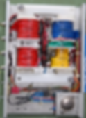
Having read what you've said about the function of the VIC and tuning of the cell etc, can you explain how those principles fit into the below schematic for Stan's simple bifilar system.
You will see that both coils lengths are the same and there is no primary, it is fed with rectified AC voltage in bursts using a gate. The voltage is 0-115vAC probably
using a variac.
Can you explain to the forum the phases of the bifilar, each coils relationship to each other and their relationship to the cell and why Stan has written 'Amp inhibiting circuit (without amp influxing)'

That's a good photo to share, I was going to share it later, but since you already have I will talk about it.
First: it shows that the chokes does not have to be on the same core material as the primary and secondary. You will find a few more to prove this in the Tech Brief.
Second: It shows a balance coil design which leaves you with only one variable left that you can make adjustments with. (which is the capacitors) Which he used tubes that he could slide up and down to make adjustments with along with a flat plate cell that is a variable to tune the system.
Third: The l2 choke is always an amp inhibitor until the system hits resonance them and only then will it react with the other coils.
========================
Is that second stage (resonance) automatic when the voltage goes up to a certain level or we have to do something special?
We can clearly hear Stan saying that resonance superimposes the particle impact to the polarization process rising the yeld of gas production (New Zealand house meeting vídeo)
You want that resonance to occur at your peak voltage applied to the primary and not before. That way you get all the high voltage you can produce on the secondary side when it goes into resonance.
The leakage current is what's controlled from 2 to 11 or 12 volts.
it's automatic once tuned
the L1 choke and cells has to be designed to setup the amp leakage along with Frequency.
Let's take Stan's primary for instance:
It has 10.5 ohms in the coil of wire used because he wants a 500 turn on the primary.
The wire he uses is rated at 1.2 amps.
in order to get 1.2 amp in the primary you just take 10.5 ohms and a 220 ohm resistor in parallel with the coil and it will give you 1/(1/220+1/10.5)= 9.97 close enough to 10 ohms then you take 12volts/10ohms=1.2 amps
You don't want to fool with your turn count ratio.
Stan used the wiper arm on L2 to regulate the voltage on one set up but on the bifilar set up there is no regulator apart from the plates.
That would mean the plates would need to form a plasma ark to create a voltage dump so that the reactance of the cell could be matched. Here is how I think Tesla did it:
Anyway i'm hogging your thread, sorry i'll just be on the sidelines from now on.
I want to put to rest what the L2 choke is:
I haven't told this to anyone so your going to see it here for the first time.
It is a built in Phase-Shifter Circuit in the VIC, It is for the purpose of providing a desired phase
shift in the output voltage compared with the input voltage.
Depending on the value of the capacitor and the value of the variable resistor or (inductor) you can determine the phase shift you want.
Kinda looks like the Frequency doubling Stan talks about, don't it?

I just cant understand why it is looking like na AC wave, swinging above and beyond the 0V, if I remove the gating I cannot see the step charge rising
Remember you'll only see the step charging as the water is being displaced. Depending upon the parameters you have, this may happen so fast you may never see it unless you have a nice DSO with a lot of memory.
The idea of keeping it simple means essentially to just run the cell full throttle--let it produce all it can. Gating is not required for this.
With gating, you are actually creating a condition of start/stop on the cell continuously, instead of just letting the voltage rise on its own.
Gating is pretty important when you are trying to maneuver your buggy into a garage packed with equipment; so is voltage control on the primary. If you're hammer down on the open road, the input voltage will be max at 12 volts and gating shut off.
Gating manipulates the production rate; voltage control sets the energetic value of the gas. Both together allows you to control an engine perfectly for the conditions.
I want to put to rest what the L2 choke is:
It is a built in Phase-Shifter Circuit in the VIC,
It is for the purpose of providing a desired phase shift in the output voltage compared with the input voltage.
Ah Hah! THIS IS CORRECT
That's what I suspected. Like I've said before, timing is everything.
Look at where that red line is. Do you see your voltage required to get electrolysis started? I do.
And since it's timing related, you know what that means--changing the running frequency will raise heck with your desired phase shift.
So you have to get the running frequency nailed down before you attempt to adjust the negative choke or all bets are off.
You have to be able to control the phase shift it in Stan's system.

You are exactly right about that Matt!!!!! and at hammer down and if the gas pressure gets to high in the cell the
gas management card shut the cell down to a preset voltage but never turning it completely off and once the cell drops to a low pressure per-set value it turns the cell back on again.
You have to be able to control the phase shift it in Stan's system.
Merc, if you dont know much about the phases and what it dose with C and L do read up on it, you will need to know about it, google "Power Factor" and r3ead up on it,
see les banki also here on gas control . basically it is controlling the rail pressure
also read up on it here find the sections related to L C and Resonance, and Power factor.
http://open-source-energy.org/rwg42985/russ/books/Hawkings%20Electrical%20Guide%20Full%20Set%20Vol%201-10.zip
BACK HERE
if you under stand phase shift, sorry for extra information, for others who do not know the relationship between voltage and current, do read up on it.
Ronnie, i have a simple Question. explain how and why the diode is in there. we know we are trying to make DC not AC Correct?
for for me the diode dose may have more reason than meets the eye.
you have to be able to control the phase shift it in Stan's system.
Like hwsaid timing is everything.
And for this circuit, timing is handled by the length of wire.
You have an signal originating from the secondary, one side heads down the positive choke; the other down the negative choke.
Now one might think where these two signals meet at the WFC, you have maximum voltage separation and that's true, at resonance. But you don't have resonance until the water is displaced.
What you have is a direct short through the water. In essence the output of both chokes are shorted together at this stage in the operation.
That's a no-go all the way around.
But we still have this little trick we can play and that is shortening the length of wire on the negative choke.
So,we say this is due to small diameter inner tube to outer tube diameter.
Let's suppose we have a center-tapped secondary and at that center-tap we connect the ground of our two-channel scope as a reference point.
Now we connect probe-A to the output of the positive choke
and probe-B to the output of the negative choke.
What should we see?
If the two chokes are equal length, we'll see two identical signals, perfectly in-phase.
Make sense? The signal has to travel equal lengths of wire through each choke and therefore they will arrive at the same point at exactly the same time.
Now what happens if we shorten the negative choke (take off turns)?
You don't suppose we'll see a phase shift do you?
We should.
The signal from the negative side of the secondary should get to the output of the negative choke first.
So now run a differential between probe-A and probe-B.
You should see a voltage there.
If that voltage exceeds 2 volts per cell, bingo!
You have the start of electrolysis in your WFC.
Get to that point and you're off to the races.
So now do you see how to tune the negative choke with water in the WFC after you have already tuned for resonance with high voltage on an empty (dry) WFC?
The thing to keep in mind with Stan's technique,
you are only creating just enough phase shift to squeak out a few volts to start electrolysis; once resonance takes over,
these few volts are far overcome by the thousands of volts when the water is fully displaced in the WFC.
The little bit of voltage loss due to this phase-shift becomes negligible.
Yellow == Primary
Green == Feedback
Blue == Secondary
L1 is next to Secondary,
L2 is up by the primary.
one is in phase one is not.
"So now do you see how to tune the negative choke with water in the WFC after you have already tuned for resonance with high voltage on an empty (dry) WFC?"
I never thought to tune with a empty cell or..... set the offset to 2v
Great
That's 2 volts per each cell within the WFC. So if you have a six cell WFC, 12 volts should do it. Remember, cells are connected in series.
DC into the primary....but AC will come out /or into the chocks
by way of the WFC.
Also there is also ringing from the coils. that often means it will go below the 0 reference line. DC normally will not go below it, that is not a fact! that is my experience with these coils for what ever it is worth.
here are some examples.


Nav, you remove turns from L2, that is the " wiper arm" its a thing you tune by removing turns a few at a time ( lets say 25 at a time) until you see the results your looking for. Matt explained this quite well above.
mentioned that if we centre tap the secondary, remove a few turns from L2 then you should see a differential of 2v per cell. I have a few questions. Firstly, how could you do this with a bifilar where Stan mentions the coil wires are the same size, how do you get your 2v?
Secondly, if you centre tap the secondary and use it has a ground then place scope probes across L1 and L2 are you not just measuring the the potential difference in coil length and therefore voltage?
Of course remembering that 3 coils and different tap points are similar to 3 phase transformers with their respective wondering about of potentials.
Here is a couple photo's of the phasing and how the coils are connected. Hope this helps everyone and answers a few questions. Can you tell which coils are aiding and opposing each other?


Question about the choke coils being the same.
The way I can answer this is.
As you can see in plain sight in the photos above, there is a B+ and B- voltage. (Example B+ 500 volts and B- 500 volts. (If the choke coils are of equal value)).
In a perfect situation, if the L2 choke has the right amount of resistance in it to stop current flow, and because the blocking diode which only conducts electrical energy in one direction. During pulse off time it also would stop current flow back into the secondary to prevent shorting of the secondary.
We don't want a perfect situation, we want electron movement in the cell. We want what Stan calls (Electron Bounce) which is electron movement within the cell from plate to plate during On time and Off time.
Since voltage is pressure, we can create this electron movement by having two different voltage pressures. (Example B+ 500 volts and B- 450 volts).
Can you tell which coils are aiding and opposing each other?
Should they be aiding? Or should they be opposing (bucking)? The two chokes that is.
I can also see the L2 coil appears to have fewer wraps of wire. At least is looks a bit smaller in diameter to me.
the secondary and L1 are aiding each other
and the
secondary and L2 are opposing each other.
That's how you get a B+ voltage and B- voltage.
Compare the two photos bove and you can see the aiding and opposing.
The second photo came out of the Grobb book if you want to look it up
. It's in the chapter 19 Inductance. It will also teach you how to calculate the mutual inductance of aiding and opposing coils.
I'm not getting into the Math of it all, Right now I just want everyone to be able to Identify all the working parts of the VIC.
I can also see the L2 coil appears to have fewer wraps of wire. At least is looks a bit smaller in diameter to me.
Primary (Yellow) -> 10.5 ohms
Feedback (Green) -> 11.5/11.1 ohms
Secondary (Blue) -> 72.4 ohms
Choke 1 (Red) -> 76.7 ohms
Choke 2 (Red) -> 70.1 ohms
AWG 30 resistance to length values:
Primary (Yellow) -> 10.5 ohms / (103.2 ohms / 1000 feet) = 101.744186047 feet
Feedback (Green) -> 11.5 / (103.2 ohms / 1000 feet) = 111.434108527 feet
Secondary (Blue) -> 72.4 ohms / (103.2 ohms / 1000 feet) = 701.550387597 feet
Choke 1 (Red) -> 76.7 ohms / (103.2 ohms / 1000 feet) = 743.217054264 feet
Choke 2 (Red) -> 70.1 ohms / (103.2 ohms / 1000 feet) = 679.263565891 feet
Source: Dynodon's Stan estate data sampling. Continued:
http://open-source-energy.org/?topic=119.msg2559#msg2559
Primary to secondary ratio is 1 to 7.
Further note you remove turns from L2, that is the " wiper arm" its a thing you tune by removing turns a few at a time ( lets say 25 at a time) until you see the results your looking for. Matt explained this quite well above.
if you remember Stan saying in one of his video's he was talking about a tv and how you adjust the B+ voltage. You can do this either by taking turns off the L2 or add turns to L1.
But for the Math of everything to keep B+ higher than the B- and to keep it equal and balanced, This goes back to what Nav was talking about when he was stating the coils are matched.
What ever you take off the L2 it must be added back to L1 if that makes any since.
That way you only take off half of what you need on L2 and add back to L1. Man this VIC is a complicated little animal for it to be nothing but a bunch of wire coiled up on a core.
Lol The biggest thing is identifying each part of the VIC and how they work together and knowing how to calculate the math for each part to come up with a working end result when your done.
You must know what the end result needs to be before you even start.
I have described the end result in my posts, so that ought to give some insight of what everyone should be working towards.
You want, as in Stan words (Voltage stimulation) (Electron Bounce) (Electron Movement) (Current Flow) what ever the term you want to use along with High Voltage, within the cell but not get back to the Secondary that's the end result.

So what you're saying is that L2 as an opposing current direction to the secondary because both negatives appose each other
but because L2 has less turns there is leakage current and voltage and it is the leakage voltage that finds its way to the cell while the vast majority of the current is choked by L2 and secondary cancellation.
Brilliant, I should have realised this when I did my bucking coil testing and found leakage voltage.
If we hit resonance during pulse off time, the voltage is expotential and not linear,
Do you think Stan took the flyback transformer from a tv and this is where the technology has come from? Possibly adding current inhibiting into the circuit later?

In this drawing below I have separated the cores for a reason. First I want you to take notice of the Primary and L2 choke is on the same core coupled together.
Next the Secondary and L1 choke is on the same core coupled together. Take notice of the capacitor, It is what brings everything together (other than the magnetic field) that cause the coils to interact with one another.
With a dead short this want take place, once again you must remove the dead short in the capacitor before any interaction of the coils will occur.
You have one transmission line from the secondary and the L2 choke that couples the secondary to the L2 choke.
The secondary and L1 choke is already coupled by being on the same core. So therefor besides the magnetic coupling, it takes the capacitor as well to bring everything together.

The priciple is definately based on the flyback transformer.


This is an important fact
When you pulse the primary and are wondering which wires go where, you must make sure in testing that
when the primary is pulsed the secondary wire which goes to the diode MUST produce NEGATIVE charge and reverse bias the diode.
When the primary is switched off the coils will switch polarity and the wire going to the diode will turn POSITIVE and forward bias the diode
Principle
Inductor & Transformer Theory
Flyback circuits repeat a cycle of two or three stages; a charging stage, a discharging stage, and in some applications idle time following a complete discharge.
Charging creates a magnetic field. Discharging action results from the collapse of the magnetic field. The typical flyback transformer application is a unipolar application.
The magnetic field flux density varies up in down in value ( 0 or larger ) but keeps the same ( hence unipolar ) direction.
Charging Stage:
The flyback transformer ( or inductor ) draws current from the power source. The current increases over time. The current flow creates a magnetic field flux that also increases over time. Energy is stored within the magnetic field.
The associated positive flux change over time induces a voltage in the flyback transformer ( or inductor ) which opposes the source voltage. Typically, a diode and a capacitor are series connected across a flyback transformer winding ( or inductor ).
A load resistor is then connected across the capacitor. The diode is oriented to block current flow from the flyback transformer ( or source ) to the capacitor and the load resistor during the charging stage.
Controlling the charging time duration (known as duty cycle) in a cycle can control the amount of energy stored during each cycle. Stored energy value, E = ( I x I x L ) / 2, where E is in joules, I = current in amps, L = inductance in Henries.
Current is defined by the differential equation V(t) = L x di/dt. Applying this equation to applications with constant source voltage and constant inductance value one obtains the following equation; I = Io + V x t / L , where I = currents in amps, Io = starting current in amps, V = voltage in volts across the flyback transformer winding ( or inductor ), L = inductance in Henries, and t = elapsed time in seconds. Note that increasing L will decrease the current.
Stored energy will consequently decrease because effects of the current squared decrease will more than offset the effects of the inductance increase. Also be aware that the flyback transformer ( or inductor ) input voltage is less than the source voltage due to switching and resistive voltage drops in the circuit.
Discharge Stage:
The current ( which creates the magnetic field ) from the source is then interrupted by opening a switch, thereby causing the magnetic field to collapse or decrease, hence a reversal in the direction of the magnetic field flux change ( negative flux change over time ).
The negative flux change induces a voltage in the opposite direction from that induced during the charging stage. The terms flyback or kickback originate from the induced voltage reversal that occurs when the supply current is interrupted. The reversed induced voltage(s) tries to create ( induce ) a current flow.
The open switch prevents current from flowing through the power supply. With the voltage reversed, the diode now permits current flow through it, hence current flows into the capacitor and the load across the capacitor. If current can flow, then the resulting flow of current is in the direction, which tries to maintain the existing magnetic field.
The induced current cannot maintain this field but does slow down the decline of the magnetic field. A slower decline translates to a lower induced flyback voltage. If current cannot flow, the magnetic field will decline very rapidly and consequently create a much higher induced voltage. In effect, the flyback action will create the necessary voltage needed to discharge the energy stored in the flyback transformer or inductor.
This principle, along with controlling the duration of the charging stage, allows a flyback inductor to increase or decrease the voltage without the use of a step-up or step-down turns ratio. In the typical flyback circuit, the output capacitor clamps the flyback voltage to the capacitor voltage plus the diode and resistive voltage drops.
For a sufficiently large & fully charged capacitor, the clamping capacitor voltage can be treated as a constant value. The equations V(t) = L x di/dt, and I = Io + V x t / L can also be applied to the discharge stage. Use the inductance value of the discharging winding and the time duration of the discharging stage.
The time will either be the cycle time minus the charging time ( no idle time ), or the time it takes to fully discharge the magnetic field thereby reaching zero current. The cycle time equals the period which equals 1 / frequency.
Idle Stage:
This stage occurs whenever the transformer ( or inductor ) has completely discharged its stored energy. Input and output current ( of the transformer or inductor ) is at zero value.
OTHER PRINCIPLES OF OPERATION
Equal Ampere-Turns Condition:
A magnetic field is created by the current flow through the winding(s). The current creates a magnetizing force, H, and a magnetic field flux density B. A core dependent correlation will exist between B and H. B is not usually linear with H. By definition H is proportional to the product of the winding turns and the current flowing through the winding,
hence ampere-turns. In classical physics, the magnetic field flux cannot instantaneously change value if the source of the field ( the current flow ) is removed. When the source current is removed from the flyback transformer ( or inductor ) the charging stage ends and the discharge stage begins.
The value of the magnetic field will be the same for both stages at that point in time ( cannot instantaneously change to another value ). The same magnetic core is used for both stages, hence if the magnetic field is the same, then the magnetizing force, H, must be the same. Consequently the ampere-turns at the end of the charging stage must equal the ampere-turns at the start of the discharge stage.
If there are multiple outputs then the total amperes turns of all outputs at the start of the discharge stage must equal the ampere-turns at the end of the charging stage.
The same condition applies at the start of the charging stage. The total ampere-turns of all outputs at the start of the charging stage must equal the ampere-turns at the end of the discharge stage. Note that there are zero ampere-turns at both the start and end of an idle stage when an idle stage exists.
Zero Average Voltage:
During steady state operation, the average voltage across the charging winding must equal the average voltage across the discharge winding, or equivalently, the volt-seconds of the charging stage must equal the volt-seconds of the discharge stage.
If not, flux density increases over time and the core saturates. Assuming a 1:1 turns ratio, then from V1 x t1 = V2 x t2 one can obtain t1 / t2 = V2 / V1 for both continuous and discontinuous modes of operation. For continuous mode operation, t1 + t2 = 1 / operating frequency.
Zero Average Voltage:
Power out cannot exceed power in. Sum up output power ( V x I ) of each output at maximum steady state load plus allowances for parasitic output power losses ( diode and resistive losses ). Divide power in watts by operating frequency.
The result is the energy in Joules that must be discharged each cycle into the output storage capacitor during steady state operation. It is also the amount of energy that must be added to the flyback transformer ( or inductor ) during the charging stage.
The energy being transferred equals ( Ipeak x Ipeak â Imin. x Imin. ) x L /2. If operating in the continuous mode, the stored energy will exceed the energy being transferred because the starting level of stored energy is above zero ( Imin. > 0 ).
The flyback transformer ( or inductor ) must be designed to handle the peak stored energy, Ipeak x Ipeak x L / 2. The power source will have to supply the transferred energy plus the parasitic switching and resistive losses of the charging circuit, plus some power allowance for transient conditions. Take this value and divide by the power supply voltage. The result will be the average input current.
http://www.butlerwinding.com/flyback-inductor-transformer/
Great read concerning what happens in Stan's VIC, take note of what is said in the discharging stage statement:
The induced current cannot maintain this field but does slow down the decline of the magnetic field.
A slower decline translates to a lower induced flyback voltage. If current cannot flow, the magnetic field will decline very rapidly and consequently create a much higher induced voltage.
Stan creates opposing negatives and opposes current so that the above statement comes true.
The resistor across the primary ensures that the magnetic field collapse across the primary is quick enough for high voltage to be maintained in the secondaries.
Look what people are doing when they build flyback transformers for jacobs ladders and such. They always solder a 220 Ohm resistor across the primary.
Here lies the basic principle:
If you allow the field to collapse slowly, the induced voltage will be low and the current will be high.
If you block the current and collapse the field quickly then the current will be low and the voltage high.
TV flyback transformers now have series coils and diodes built in and can produce 30kv output from 12v input @ 300mA. But take note, if they don't spend the voltage at the same rate that it is created then they destroy themselves quickly which is impedance lingo.
So in essence the VIC is a tv flyback transformer using the reverse voltage bias principle but further blocks the current with L2 opposing the secondary current then uses transmission line impedance matching principles.
Also allowing it to operate at the self resonant frequency of its secondaries which incidentally is also a principle used in more efficient tv flyback transformers.
TV's are tuned so that the 30kv from it's flyback circuit is always fully used by the tv screen and a dump capacitor.
If we build a capacitor and we need to tune it to our flyback circuit then we too can build a dump to tune it. A big spark gap would be useful.
Here is a typical flyback with the tip 3055 and a 240 Ohm resistor, looks remarkably similar to stans primary set up doesn't it? I wonder what the resistance is of a tv flyback secondary?
Has Stan just rearranged this schematic?

With a dead short this want take place, once again you must remove the dead short in the capacitor before any interaction of the coils will occur.
Excuse me for not seeing the forrest for the trees here, but removing the dead short means in fact applying some Faradic brute force electrolysis on the WFC, which creates a layer of gas bubbles on the cell pipe walls, which in effect then turns the gas itself into an isolator, thus "removing the dead short", is this anywhere near what's going on here?
Can be Achieved with Dielectric barrier
Another flyback drive circuit, this one produces 30kv@ 5 amps but no current restriction. You could fit this drive circuit onto Stan's VIC though and have current restriction @ resonance of the secondary.
Ronnie has shown us how to restrict current using L2, this was the stalling point for most, now the gloves are off you can fly. We can take the drive circuits and flyback circuits out of tv's and make this work, you don't have to build stan's circuits.
Stan's circuits are needed to make it work the way he intended it to. Safely and automatically.
You still can do, but there are other ways like thus which can still be controlled safely. It's understanding the principle at this stage which is important.
Superb reading here:
http://boginjr.com/electronics/hv/flybacks-guide/
Boy oh boy is this getting good Ronnie. You were right, Stan took his B+ jargon from tv circuitry talk.

A Guide to Flyback Transformers
Unless professionally required, a lot of high voltage enthusiasts do not wind their high voltage transformers at home. This task would be nearly impossible to do without proper coil winding, insulation potting and vacuum-sealing machinery. Thus, high voltage transformers from everyday electronic appliances, such as CRT TVs and computer monitors, microwaves, automobile ignition coils etc., are used. This article will be regarding the so-called “flyback transformers”, a well-known term in the high voltage hobby, and their various types of construction and output.
Firstly, what is a flyback transformer? Well, if you take a peek into every classic “fat” CRT television or monitor, whether vintage or modern, you are going to find one. Basically, it is a ferrite transformer with an air gap and 2 or more coils, sealed in epoxy or interlaced in an insulation paper, whose outputs go to the television screen. These transformers run on ultrasonic frequencies, mostly in the 15-50 kHz range, and are designed to provide 15 to 35 kilovolts for the screen’s electron beam. This output is easily located; it is the thick red wire with a scary looking suction cup connected to the screen… Newer flybacks also have, in addition to numerous other things, a high resistance resistor cascade, dipped in epoxy, to provide information about the high voltage output to the internal driving circuitry of a TV or monitor. These flybacks also have two or three “knobs” (potentiometers), to adjust the focus and brightness of the electron beam. Depending on age of the TV or monitor which you might have disassembled, you are going to meet with these types of flyback transformers:

These are 6 different kinds of flyback transformers which I have met with.
Type 1): These 6-8 kV AC flybacks were used in conjunction with a voltage multiplier, like this one.
Absolute maximum allowable output voltage 10 kV~ at 15 kHz (PAL horizontal frequency). Prevalent in many Czechoslovak, Soviet and other color television sets of the 1980s. Has many layers of insulation foil. Primary windings are located below the secondary. Use these flybacks for all the lower voltage, higher current needs. Will sustain at least 500 watts of output power, if ran in short periods or with adequate cooling.
Type 2A): A 10 kV AC compact flyback for portable black and white television sets with secondary dipped in epoxy. Maximum output voltage 12-14 kV AC. Used with an external rectifier block. Not suitable neither for higher voltages nor high output currents.
Type 2B): The same as 2A, however with the high voltage rectifier integrated to the secondary, so it is a DC flyback. Has slightly less secondary turns. Used in TESLA “Merkur”.
Type 3): Prevalent in all black and white sets from early 1960s up to circa 1978. This AC flyback has the secondary dipped in epoxy and is similar to a kind colloquially named the “disc-shaped flyback”. It was used along with a vacuum tube rectifier, like the DY86, DY87 or 1Y32. This particular type has been made by the Czechoslovak TESLA in mid-70s and the maximum output voltage was something over 20 kV AC at 15 kHz. Used in my first quasi-resonant driver.
Type 4A):
These DC flybacks are found in every CRT computer monitor and are called the DST flybacks (diode-split transformers) because of the several high voltage diodes and secondaries inside. In addition to the high resistance resistor cascade and focus/screen tuning potentiometers described above, these kinds have an integrated high voltage filtering capacitor (few nanofarads at >=30 kV), or – optionally – a HV capacitor for dynamic focus. Because of the capacitor, these flybacks can hold a charge enough to shock you even after a week.
The bottom pins will start arcing over, also because of the internal capacitor, if the flyback is overdriven above 30 kilovolts.
Type 4B): Like the 4A, these DC flybacks are also diode-split (DST), however these are found in every modern CRT TV-set from mid-90s and onwards. These have just two screen-tuning potentiometers and no internal capacitors whatsoever, so they can be safely overdriven to circa 50 kilovolts DC; albeit some beefy ones might give you even 70-80 kV with ease. This flyback type has been used in my Monster flyback driver.
A practical problem with DST flybacks – types 4A and 4B in the picture – would be locating the high voltage return (ground) pin on the bottom. If you’re lucky to find yourself a datasheet for your particular flyback (or its HR-marked equivalent name in an online conversion table), then it is a cinch.
If that is not an option, you can try the circuit tester published here to find it. As a last resort, you can try constructing a low powered flyback driver, like the “2n3055” single-transistor one, then powering it on and placing the anode wire close to the bottom pins. You know you have found the right pin to which the anode makes a continuous arc.
And that is about it, folks. Hope this article explained some practical facts 🙂
Tagsac, capacitor, dc, dst, flyback, flyback driver, flyback transformer, guide, high voltage, how-to, lopt
Russ i know what you are saying...but i'l give you a practical example of using tv flyback cores.With those flyback cores i get inductances of 10H to 13H.To get stans values you have to have a very big distance between the cores,so big that you loose almost all the mutual coupling so its not that KISS
Why Vic Transformer
controls not on main board?

Now we know why Stan placed his
-
tip 3055
-
voltage regulator
-
resistors
in close proximity to the primary and the pick up coil as in the below picture.
I always wondered why the tip 3055 wasn't on the main board and the
voltage reg too.
It's because they are part of the most common flyback driver circuit ever made
and the diode is also part of that famous tv circuit that's been around since the 1940's more or less.
Stan has taken this circuit which has a principle of reverse biasing the diode during charging then forward biasing during discharging,
he's rebadged it completely and cleverly hidden it from the patent office.
In other words he found out a tv hv driver could charge a cap of his choice as long as he matches the drive circuitry just like a tv drive circuit is tuned to the cathode it drives.
Kinda disappointed really in the end that its turned out this way
but it's opened up aladin's cave and made things a whole bunch easier.
If people can't get the cell working now then I don't know what to say.
2n3055 on Meyer circuit Works on Voltage amplitude circuit regulation only, coupled
with one of the TIP120.
It is not good to speculate other things and see others that aren't there, sorry.
Let's weigh up the evidence shall we.
1. Tv flyback circuits contain typically, a 3055 transistor, a voltage regulator, a resistor of about 220-240 Ohm value and a diode on the output of the secondary.
A primary coil, a pickup coil and up to 3 in series secondaries.
2. Stan's VIC which he produced the most contain typically a 3055 transistor, a voltage regulator, a resistor of 220 Ohm value and a diode on the secondary output, a primary coil, a pickup coil and 3 in series secondaries.
3. Both are capable of producing massively high voltages up to 50kv and some tv flyback transformers can produce 30kv for less than 500ma especially if they have in series multiple secondaries.
I'd say that kinda wraps it up, oh I almost forget the most important thing:
both deploy the principle of reverse biasing the secondary on charging
and forward biasing the secondary on discharging.
====================
Why the VIC is Special Transformer
I wonder what the resistance is of a tv flyback secondary?
I think Stan probably got many of his ideas from conventional TV circuits, but there are some fairly profound differences. One of which is the turns ratio. And the second is the core gap.
I think you'll notice most TV flybacks have many thousands of turns of very tiny wire on their secondary, which would translate into very high DC resistance.
So as you have heard from Ronnie, this form of drive circuit might be able to sustain gas production, but it would never be able to handle enough current to initiate it.
Same would be true for using automotive ignition coils.
The VIC is a special breed, tailored specifically for the WFC.
Just think about the turns ratio aspect. How would you get 20kV from 12V when you only have a step-up ratio of 1 to 6?
This is where the math, the timing and the properties of the VIC components take
things to a whole new level.
So a TV flyback circuit driving a WFC? Probably not. But a VIC driving a TV tube? That may be quite possible. And I wouldn't be a bit surprised if Stan stumbled into just such a circuit working with military radar equipment. Maybe one of those old radar scopes use the VIC. The manual for such scope might even refer to the driver circuit as a Voltage Intensifier Circuit. Mr. "Keep It Simple Stupid" himself, surely wouldn't attempt to re-design from scratch something he already knows exists. He'd just use it with a few tweaks.
The reason I bring this up is because military equipment is typically (or used to be) hardened for battle. It wouldn't use thousands of turns of delicate super thin wire. So to meet the specifications of the Air Force at that time, I'm sure a better circuit was devised capable of being beaten up and still work in the field. The VIC is the likely outcome of that engineering feat. Probably dead-n-gone now is an engineer that originated this circuit and knew exactly what all it could be used for. It's only fortunate for us, Stan figured out what else this could be used for. And now Ronnie is bringing it to the table for us to figure out as well.
================
If a FBT is connected push pull with 2 trans then it is functioning as a transformer with a winding ratio. if FBT is use as a storage device only one trans can be used and there's no winding ratio .
because of the sec HV diode , you can guess what the R measurement is ??
Lets just say a cathode tube absorbs 30kv/ms@15khz and it's dump
capacitor accounts for +10% per ms.
If your cell is only capable of 20kv/ms@15khz before you reach a dielectric breakdown and failure then you need to dump 10kv/ms to either ground or across an anode and cathode.
If you look at one of Stan's schematics he has such a set up in parallel to his cell called an exciter array which has an adjustable width between the surfaces,
Ronnie has already mentioned it.
Tesla did it with spark gaps then adjusted them in or out which matched the impedance of what ever he had in parallel with the spark gap,
Stan's cell didn't mind where the voltage was coming from as long as it could
handle the speed and pressure it came at.
I'm not sure about Don but there isn't much i've read in Stan's papers which mention 220 ohm resistors, voltage regulators and tip 3055 in the VIC but I do know this.
There are just far too many coincidences in Stan's VIC and a TV flyback for it to be a accident. I'm just not going to buy it.
What does it say on the transistor in the below VIC x-blade, it says 2n-3055, its in the VIC, its not fiction, its connected to the componants of the VIC, there is a regulator in there too and a 220 Ohm resistor just the same as most TV flybacks. There is also a reverse bias diode in the picture just the same as is built into a modern tv flyback.

3055 is not the driver, it is part to the analog voltage amplitude control.
Check it out
You havn't answered the question AGAIN, voltage can be controlled across the primary in many different ways.
Stan can control the voltage amplitude to the primary from the PCB, anyone can build circuits to do that using mosfet drivers.
Stan used the tip3055 for a specific reason, what is it?

I've messed about with tv flyback transformers and drove them before with PWM and the transistor drive circuit, doing jacobs ladders and stuff with 30kv but generally speaking they are current indusive and don't last long before you blow out the transformer but there is a reason behind that.
While ever you are doing experiments such as jacobs ladders you are constantly changing the input to output impedance ratio, this will eventually cause reflected energy to be aimed back into the secondary and burn it out.
Stan's Vic, the way it is constructed is a much more stable platform, the impedance you aim to match is more controllable and you have much more parameters to play with than just producing a basic set up.
But I can assure you of this: If you took a modern TV flyback transformer of the advanced kind that can produce 30kv for less than 500ma and you impedanced match it with a PLL to a cell then it would work the same way it produces 30kv for a cathode tube and is tuned to the cathode.
Voltage is voltage and impedance is impedance no matter where they are.
, voltage amplitude control is connected on the + of the primary, there is a second TIP120 with the collector to the - of the primary coil.
Lets just say you were a policeman x-blade trying to solve the case of the missing componants someone stole from a flyback transformer factory and you came across a pile of Stan's Vics, what boxes could you tick.
1, primary - tick
2, 3 secondaries per VIC - tick
3, tip 3055 - tick
4, 220 ohm resistor - tick
5, voltage reg - tick
6, feedback coil - tick
7, reverse voltage bias diode - tick
8, air gap in core - tick
Occam's Razor says when you have explored all avenues and come up with nothing then the most simple explanation is always correct and that is that Stan copied a tv flyback. Hard to take but that is what it points at.
I'm not disputing that x-blade, i'm saying that all the parts around that area of the VIC are associated with a flyback driver circuit and are replicating a flyback driver combined with the primary and the feedback coil.
I told you that tv flybacks produce upwards of 30k with as little as 300ma input and if we are smart enough we can use that information for the good, I also suggested that Stan's schematics and indeed his VIC resembles very much a flyback with all the parts neccessary.
Let me get one thing clear: tv engineers managed to produce 30k volts into a cathode tube without any of it relecting back into the flyback secondary, that tells you they impedanced matched the source to the load successfully because guess what - tv's last for years.
All I can say is,
"It takes gas to make Stan's gas".
It's a lot easier to take a gas through these stages than it is to try to take water through these stages.
Water is only used in the V0 to Vn stage and to keep the process going. It even states Gas Ionization not Water Ionization.

My comparison to tv flyback circuitry is useful information because it explains how one piece of apparatus can maintain 30kv on a cathode without blowing up. Whether we like it or not x-blade we are struggling to maintain a similar voltage on a cell without it blowing up, indeed at the moment no one seems to have any voltage on a cell at all. That means its 1-0 to the tv engineers does it not?
Maybe we can learn things from them hey?
Ronnie told us not to throw high voltage at the cell without considering inhibiting current first and impedance matching the VIC to the load because of standing wave ratio's.
That doesn't mean flyback transformers are not in the ball park, it means they have to be tuned too.
You bring up some great points.
I don't see the VIC as a flyback though.
The reason is because the flyback produces voltage in a different manner than the VIC.
A flyback depends on short high current pulses through an inductance...When the magnetic field collapses it produces a high current through the inductance. V=L *di/dt shows you how the voltage is produced.
Yes Stans explanations are very similar...But I don't believe they describe a flyback.
In the VIC the voltage is generated by a small current flowing through a large reactance. V=i * XL, V=i * XC
Do the math used for basic transformers....You'll find the turns ratio produces around 60V across the secondary coil....In a series resonant circuit at resonance the only impedance is the resistance in the circuit (around 220 ohms for the 3 coils).
Take 60V/220 ohms = 270mA .
Now...Stan states the cell uses up to 20kV
How much reactance would it take for the 1.262H choke to produce 20kV?
20kV/.27A = 74,000 ohms impedance
Now....What is the impedance of 1.262H at 10kHz?
Answer: 79,000 Ohms
That shows you using the actual measured valued of Stan's VIC & L1 choke that just below 10kHz the circuit will produce 20kV across the cell...If it's at resonance, that's the hard part!
Coil Phase Direction
Both of those photo's are identical to each other, and they are correct.
.png)
.png)
Again both drawings are the same. The top one of STAN'S is a wire diagram and mine is actually on the Vic as drawn. Stan's drawing is not on the Vic it's a diagram of the Vic circuit.
Stan states in the tech brief that all coils are aiding each other. for example this would be my format:
1. A primary pulse is sent to the VIC and during pulse on time this is the scope shot of current and voltage, the voltage has X relationship to current (phase relationship of current and voltage in the primary)
2. When the primary is at pulse off the scope looks like X and the voltage and current have now changed X value: This tells us what the resistor is doing on the primary during pulse on and off etc.
3. Secondary during pulse on has a scope shot like X and here is the phase relationship between voltage and current and here is the difference between the primary phases and secondary phases.
etc etc etc.
What this does is help people build up a understanding how everything is ticking because without it you can't up scale or down scale or see relationships that may be very significant including phases. Tesla had a mathematical mind, he understood the principles of electricity in his mind but we don't have those qualities. If we are tuning radio's for example, it is almost impossible to tune the pll circuits and the vfo, ocillator etc without a scope or other means of syncronising stuff. Watch Stan's vids of himself and his brother with the boards connected to their scope, without a scope you are screwed basically.I gave the math that shows how to match the line to the load and it all adds up. And most everyone just threw it to the side like it was nothing. Believe me if you don't know how to match everything you don't need a scope in the first place. And from what I have seen so far no one has ever figured out how to match it all up. Jumping form one thing to another want get you a working cell at all. My suggestion is to leave the soldering iron and scope and the wire and bobbins all alone until you figure out what to do with it all.
"At start up, in this example, current draw through the water cell will measure about 25 milliamp; however, when the circuit finds a tuned resonant condition, current drops to 1-2 milliamp minimum leakage condition."
So 20kV gives minimum of 10 Mega Ohms of "impedance" for this current through the cell.
answer dbd barrier or gas layer
None of his drawings show the diode reverse biased to make it a flyback.
Yes he does talk about the chokes producing a pulse during the off time....But any inductor does that.
I can see when you look at things there are alot of similarities....But the math also works the other way.
Have you done the math to calculate the voltage that would be produced if the vic were to operate like a flyback?
Watch this video, then compare it to the drawing with the phasing dots that Stan has on his drawing.

I think he has L1 and L2 opposing the secondary to restrict current flow then the diode only allows voltage to leave in the direction of the bias.
I'm really interested to know what the secondaries are doing during pulse on time while the primary is building up the magnetic field though because those secondaries at some point will change polarity. Is the diode at reverse bias during pulse on or is it in forward bias?
If the secondaries are in forward bias then the current is restricted apart from the leakage current that exists because L2 has fewer windings.
That may be enough to allow brute force to line the cell walls with bubbles like Lynx mentioned then when resonance takes place the impedance is matched to gas not water.
But are you not still left with the problem of all 3 secondaries jumping polarity during pulse off time? Surely that jump would put the VIC into reverse bias?
exact science says it is impossible to obtain a high voltage in VIC with existing windings ratio
Correct Ris, unless you employ the concept of resonant rise.
This is why I highly recommend people build this VIC as Ronnie is describing it and demonstrate the same effect Ronnie shows here:
Do this first.
Then let's work towards the next step of initiating electrolysis by tuning the negative choke.
I'm becoming more and more convinced the VIC actually sets up a condition at the atomic level of H2O that creates stress on the molecule in a way no other device does.
We need to stick to the plan for now.
Once people have it working, then you all are free to pursue all sorts of variations.
I think what you'll find though is there is really only one mechanism at work here and until it is fully understood, any variation from this mechanism will prove to be a dead end.
So you put water in the cell I reckon. Bad idea. Run it dry and tune. At least get some sparks if possible.
I may well have the same problem with my cores and will soon know. I'm using Bridgeport Magnetics Amorphous C-cores, BMCC 50s.
https://www.bridgeportmagnetics.com/shop-category/standard-amorphous-c-cores/
I'll be wiring this as per Ronnie's direction. If with his help I cannot achieve high voltage sparks, then I'll know the cores and/or the math is way off from where I need to be. Maybe back to the drawing board, maybe not. We will see when I get to that point.
Ronnie knows a lot more about what is critical and what is not. I'm sure there is even more none of us know, so watch your step in the minefield for now and follow a path that has at least worked for Ronnie.

BUILD IT
Ronnie has given us a foundation with the DC impedance matching and it looks to me like no one has done their homework as Russ suggested we will need to do.
Seriously, did anyone spend a few hours playing with the spreadsheet I posted? If you did you will realize several things straight away. If you mess with the turns ratio, you're hosed. If you mess with the resistance on the primary side, you're hosed. If you mess with the resistance on the secondary side, you're hosed. If you add or subtract turns someplace you better balance it or... You're hosed.
So what's left to adjust?
Do you see anywhere on that spreadsheet frequency? No you don't.
How about core parameters? Nothing there either.
If you adjust the voltage when the VIC is matched, what do you see? You see the power-out still equals power-in and everything stays matched.
So we have three completely independent variables left we can adjust that will match the VIC to the cell. And the core just needs to be fairly high permeability so we don't have stray flux all over the place. That leaves two variables. Ronnie already stated to start at low voltage and tune the frequency a little at a time, then go to a slightly higher voltage and tune again. Keep doing this until you hit the 12 volts max. No magic there. Once you get up to the 12 volts, don't make any frequency adjustments or you'll fry your VIC.
Come on guys, quit bickering about needing fancy test equipment, scope shots and visual proof. The math is right there staring you in the face.
Do the homework and lets get building or rebuilding if you already screwed up.
Look at your core, figure out what wire to use, make some bobbins starting with the primary, shoot for a 1 : 6 turns ratio, plug in the numbers and try to get as close as you can. The magic is in how this thing really does what Ronnie says it does, not in building it. Ronnie has given us enough to solve that part if we get serious and crunch some numbers. That's my take on it anyway. If Ronnie has more to add that will improve this process, I'm sure he will tell us.
Matt is right, you can not fool with any resistance from either side or your screwed.
Impedance matching the line to the load was with resistance only.
Let's move on,
What I was trying to show in the impedance matching the line to the load was with resistance only. Let's say we only had the line resistance and the load resistance. But we knew the voltage to the line and the amp to the line.
We can get the watts from that.
We know we need the same watts out of the load.
but we only know the load ohms and watts from the line.
If we use the same calculation as before. All the resistance would end up on the secondary as one big coil. but still equaling out to 310 ohms when done.
Stan needed two chokes on both sides of the capacitors. What better way to do this than to take the secondary and divide it into 3 coils. Take 3.83 ohms from each coil and you have the Feedback coil of 11.5ohms
You still end up with the 310 ohms in the load side.
But now you have charging chokes to boot. You have the ability to have a LC circuit now.
You not only have amp restriction built in because Inductors can't stand reverse current.
Now that you have everything impedance matched and inductors in place all you need now is a capacitor to set up the LC circuit.
Because at resonance Xl and Xc will not have any effect on the impedance match.
I hope this helped in identifying all the working parts, and how they were calculated in.
Summary:
Without inductors, the resistance can be a secondary coil with 73 ohms and a two resistiors of 73ohms and a feedback coil of 11.5 ohms and a load of 78.54 ohms.
But replacing the two resistors with two inductors will be the same total resistance needed to impedance match the load resistance.
Questions
Ronnie, why 310? where came the 11.5 we saw earlier on this thread?
11.5 is the feedback coil. anything on the load side has to be included in the total resistance. Sorry about that, that resistance has to be taken away from all three coils for it's own resistance in its coil.
1- Why Meyer used the red for the - of the cell and the black on + (it is very clear on the Picture)
2-The diode if it was the MUR1550 the arrow is reversed, like this --|<|-- and we can see it coming the anode (back of the arrow, right leg) wired to one of the + choke.
why do you include all the coils as a load and not calculate from the chokes to cell?
Because at resonance there is no ohm value if XC and XL is tuned to cancel each other out,
So therefore it does not effect the impedance match.
The only way you have a ohm value in XC and XL,
is if there is a difference left once you subtract the two.
We don't live in a perfect world, so therefore our coils are not going to be perfect and our total resistance we need may be a little off here and there as we wind each of the coils,
So we can still use the XL and XC to our advantage to still keep all the resistance right by having a small ohm value left once we subtract the two.
That is achieved by tuning the frequency.
In other words ( a little above or below resonate frequency will add a ohm value).
That's why when tuning it is so damn touchy, and things can go south real fast.
Again that is why you want see anyone touch my cell and turn knobs once tuned and working, (Like I seen another person do), and Stan wouldn't either.
Note:
If you don't start the tuning around 2 volts on the line and work your way up,
You will indeed burn up a coil and not even know it.
And you can tune for a year and never get any voltage.
The only way you will know if you burn up a coil is to take everything apart and check the inductance of each coils to see which one you fried.
Another question will be why calculate the cell/load resistance as 78ohms
(I know thats the dialectric constant).
I have put 12v on my 1cell and its draws 300mA,on natural drinking water.so
40ohms resistance
.I will try with distilled water,i think that will get close to 78ohms.
Also, with a diode as part of an LCR circuit, true resonance does not apply.
I have a feeling the placement of the diode is what is most critical to this circuit.
It is never placed between the water capacitor and the chokes, only prior to the chokes where the voltage would be lower during resonant-rise conditions.
Not knowing for sure, just spectating, I would think this would indeed create a polarity bias.
Stan's Vic does not have a steel core, it has a ferrite core material and the vic produces frequencies in the AM range.
Thanks so much for the explanation on impedance matching
.i did not get it entirely but i re read the grobs chapter on that issue.
A few videos to help the concepts sink in:

Vic Core
Good for 10Khz looks like to me.
Talk to you more about the AL value when we talk again on skype.

Tuning Vic With Air First
That part I dont understand, if you tune it without water it will change when there is gas or water and not air.
But the dielectric constant of air and the dielectric constant of gas is a lot closer to the same. If you tune to the dielectric constant of water, you'll be way off, like on the order of 25 times, plus the resistance will be much lower when you have water in there.
You want voltage when you have a low dielectric constant in the cell and current leakage when you have a high dielectric constant, but direct electrical short.
Remember, the VIC is an ingenious little device. It has the ability to work on both gas and water, not necessarily at the same time, but it will provide the transition from one to the other if you have the impendences set correctly and the right amount of current leakage.
This is the way I understand the operation as Ronnie has explained it to me. If I'm wrong, I'm sure Ronnie will clarify it for everyone.
Remember these 3 things about XL and XC.
1. Below the resonant frequency, X L is small, but X C has high values that
limit the amount of current.
2. Above the resonant frequency, X C is small, but X L has high values that
limit the amount of current.
3. At the resonant frequency, X L equals X C , and they cancel to allow
maximum current.
Now this says everything
everyone thinks that choke coils restrict current going in cell which is absolutely incorrect

As Brad stated the total resistance of the coils of wire on the Secondary and L1 and L2 and the Re of the water is what is used to calculate the current.
As you can see the less resistance in the coils of wire and Re stays the same can raise the current. But also the resistance of the coils can stay the same and lowering the Re can also raise the current.
At resonance when XC = XL all you end up with is the resistance of the coils of wire plus the Re of the Gas that will determine the maximum current at the resonate frequency.
Using Stan's Vic and the numbers Don gave us as and example, I will attempt to show how to impedance match it all.
Question is what is the purpose of Impedance matching?
The answer is Watts in must equal Watts out. (Isn't that right Mr.Watts :clap:)
Let's start with the Primary, I have already show it has 10 ohms of impedance in it and how it is calculated.
Line(Primary) side=10 ohms
12volts/10ohms=1.2amps
1.2amps*12volts=14.4watts
Next we use a transformer (Amplifier) to match the Load side.
we need to know the total resistance of the load side.
Secondary side= 72.4+76.7+70.1+Re78.54+11.5=310 ohms
So secondary coil, plus positive choke, plus negative choke, plus dielectric property of water, plus...what's that 11.5 ohms?
Where does it come from? =FEEDBACK COIL MUST BE INCLUDED 11.5 ohms
Now that we have a total resistance of the line side of 10ohms
and a total resistance of the load side of 310ohms
Next we take the 310ohms and 10ohms and use this formula to get the turn ratio.
Ns/Np=sqrt Zs/Zp sqrt (310/10)=5.567
So we need a turn ratio of 5.567 to 1
We know our line voltage is 12volts
We can times this by the turn ratio of 5.567 which is =66.816 Load Voltage
Now we have our load voltage.
Next we calculate the load watts
using formula (66.816 ^2)/310ohms= 14.4 watts
That's how you do it. :bliss:
Corrections to above
Ns/Np=sqrt Zs/Zp sqrt 300/10=5.477
So we need a turn ratio of 5.477 to 1
Where does the 300 come from?
Shouldn't that be: sqrt( 310/10 )=5.568
We know our line voltage is 12volts We can times this
by the turn ration of 5.477 which is =65.724 Load Voltage
Now we have our load voltage.
Next we calculate the load watts
using formula 65.724 sq2/310ohms= 14.4 watts
Checking the math...
Doing: ( 65.724^2 ) / 310ohms gives =13.9 watts
A use of parenthesis would be useful, not relying on the order of operations.
============================================
Actually, this checks out! (when correcting 300 to 310)
( 66.816^2 ) / 310ohms gives =14.4 watts
Change your errors from 300 to 310 ohms.
And, change 65.724 to 66.816 load voltage.
5.477 to 5.568 turns ratio ...
One error can mess up the whole math.
Thanks haxar I fixed it. It was way passed my bedtime last night and I was just trying to get it done. If you see another mistake please fix it in my post. Thanks again!!!!!
=============================
Summary
I see some interdependence here that will take lots of do and redo to zero in on the final values. I also see how that very fact enables this circuit to function as it does.
It has a built-in feedback loop that will constantly attack the water at faster than the speed of light. If anything changes in the cell, the impedance changes immediately, faster than the water can react. This might be the whole key to it Did you ever consider that?
The turns ratio will force you to recalculate the resistance of the wire you use to get that many turns, and...
The resistance of the wire you spin on the bobbin will force you to recalculate the turns ratio.
This could turn out to be a little bit of a pain in the butt.
didn't you mention to me a while back that the turns on the chokes need to match the turns on the secondary?
So if I was to adjust the secondary, to get the right turns ratio,
I would also have to alter the turns on both chokes?
Answer
The 11.5 is the feedback coil.....and yes that is correct the chokes must match the secondary....
That's why if you take turns off the L2 they must be added back to L1.
In Stan's example secondary is 73ohms close enough, then 76ohm for the L1 and 70 for L2 if you take 3ohms off the L1 and put that 3 ohms back on the L2 you can see they all match to 73ohms.
Why does he do this?
It's to get the slight potential difference in voltage needed on the chokes.
You need to use the transformer formula to determine the primary turns, you need the Bmax, min. frequency, voltage and core section area, then the secondary is X times the primary.
The load on secondary will define the load to primary.used the wire lenght used by stan and by Ronnie on his round bobins.If i got lets say less turns than stans..the turn ratio remains the same being the same lenght if wire
So where does the 220 Ohm resistor across the primary figure in all this? Shouldn't the resistor be 300 Ohms? or is the resistor not counting the 78.54 and the 11.5 Ohms of the feedback?
volts times capacity=power times oscillations=changing magnetic field through the core all the way to the primary winding=drop all to mamps.
Stanley Meyer is a smart man
Note it is the 90 degree magnetism which restrict the amps and allows water to be pulled apart
https://www.youtube.com/watch?v=iaB5ME8kFGU
NAV
Re This IN one of Joe Cells Videos he says he makes the charges in the cell go 90 degrees
to pull apart water molecule but using neutral tube between + - tubes as the resistance.
it makes the charge go sideways in the cell , stan says very similar but most would not understand it with out comparing
to joes comment at start of this video. 16 Years Stills learning
https://www.youtube.com/watch?v=Wps3UBSXJsU&t=6s
So in order to determine where amps are restricted I would need to see the scope shots but there doesn't seem to be any
If you watch the video of the spark plug, you can see they are almost no amp draw in the primary. If I remember right about .03 m/amps. It's due to no load on the secondary due to resonance.
I just realized that I have missed a critical detail,
where in the VIC core(s) is/are the airgap(s)
you dont need osciloscope shots only common sense ,capacitance times voltage equal power,coil and a capacitor connected together easily oscillate and produce a magnetic field if you increase the voltage you increase magnetic field stronger magnetic field stops the flow of electricity in primary winding
inductors hates reverse current that's why they sound like they are frying when in resonance.
What better way to cause oscillatiion within the cell than to put an inductor on each side of the cell.
Also a resonate chart to take a look at.

Flux notes
this is how the flux is...
all coils are adding each other ( the magnetic flux is always going on one direction during the on time)
now, the Voltage and how the coils are connected is this,
the Primary and Secondary are voltage adding,
the L1, an L2 are Voltage Adding,
the Primary-Secondary VS L1-L2 are apposing. Voltage potential.
during my testing i took Aprox 5V AC 60HZ sine wave on the primary.
when connecting all the coils per the diagram on a single core... ( with out the diode) there is this 75 Degree Phase Shift. on the output signal VS the input signal.
not sure if it is helpful but just expressing my test results.
the wave form was still a sine wave.
yellow is output
Blue in input.
acts at a 1:1 almost...
when connecting all coils in adding electrically and flux adding i got a nice sync'ed AC wave form and stepping up the voltage like it should..

OK, here is a quick explanation,
this is the measurements of the 6 cell' each with out water then in series with out water.
Then with water each by them self's, then in series. ( distilled)
now you will see i took measurements with the leads connected one way, and then connected in the opposite way to see if there was any difference. ( looking at the asymmetrical capacitance )
now you will see i took measurements with 2 meters.
one with my THNGHUI TH2821A LCR meter. ( good meter) the good meter also has a ser or pal calculation function. ( i have know idea what the difference is but some times ill take measurements with PAL or SER so that's why you may see that on my note's)
the other with my LC200A ( cheep meter) the cheep meter also gives me a Frequency its checking it... you may see this next to a cheep meter reading... that's what that number is for.
the cheep meter reads the capacitance very accurately with water in the cell. the good meter dose not even come close.
when you do the calculation of the air capacitance and then * it by 78.54 you come up with the correct pF according to the cheep meter... the good meter just dose not work well with water???
the numbers 1-6 at the top are each cell. numbers 1-6 for testing.
hope this helps in some way...


theses notes were to check what happen when measuring capacitance across the cell and across the inductor at the same time.
using my cheep meter so i have the frequency it was measuring at next to the pF...
so you have " M+ to Cell- cell+ to L2A to M-"
that means i have the connections like this,
L/C meter + lead connected to the Cell - then the cell+ to the coil L2 Version A to L/C Meter lead -
i do each coil and then each change the leads around ECT.
I then go for 2 coils one on each side of the cell.
you can see my coil capacitance mesuremtns on the first page. off to the left side of the page.
only checking capacitance in this test...
coils have A and B next to them. the reason is i have more than one coil labeled L2 or Primary... ECT... they have different turns on them...
P is primary, S is secondary, L2 is L2 and L1 is L1...
I'm still going the results my self...
but one things for sure...
capacitance readings are different depending the meter connections... the different surface area is playing a roll here...
my good meter dose not calculate this correctly. its normally the same ether way i check it...


Did some bench testing myself today.
The Good.....Sunned both L-1 and S-1 to 15.6K
The Bad..Looks like the VIC needs the capacitance from the cell to tune down to 10K..Great...
The Ugly..My cell had 2-3 cells that were shorted so the capacitance was not the same across the plates.(Using the cheapo meter)
When you say you tuned the L1 and S1...
Can you explain your tuning. How your going about it?
Shorted cells. That's not fun. So your capacitance was to high.
I just wanted to make L-1 and S-1 tune the same so I tested all of my coils and found one that had more pf than the other small coils and called it S-1 than grabbed a larger coil (2,400 Turns) and called it L-1.
I put L-1 on the left side of the core and adjusted the gap on the left side only.
At about .003" the coils both rang at 16.6K with a 50pf cap added to the coil so it was not just open.
I also did this with the L-2 and the primary..Long story there.
After all coils were tuned to 16.6K I hooked it up with my cell and got nothing at 10K or less.
My goal was to try to make this thing ring at less than 10K for once.
I tested my cell like you did and found it to be shorted so I used my 4,000V air cap set at 50pf instead.
This did help and for the first time the VIC did tune to 9,700Hz. but did not ring to 10,000V.
I do not think L-1 and S-2 need to be exactly even like I had it,
I remember someone saying you don't want a perfect match here?.
The important thing is that the cell is most of the capacitance for the VIC.
It semes that my coils and cell ring at 20-22khz.
Know mader what I do it seems that it works there some what.
So one thing is for sure. The RE or resistance of water according to the 78.54 ohms must e used or te circuit to work.
Using an air cap like I have has and will change stuff. I would hope to see that I would still be able to see resonance but I think that the Vic won't work the way it was Intended to with out the water interaction...
your using the VIC connected like don's drawings and the redraw? Or something else? And on the same core?
For your information to be useful I need that data if you can make sure I know how you have this set up. Good stuff!
Im Using my beta 4 twin core that I posted for the connections..Positive on top not the way that it is posted. (beta's never work) Nothing I am doing will work for at least a 2-3 weeks, I need new bobbins for my new core (China core)
Right now I am using a makeshift C core that .... can be adjusted but I like your adjustable core better and will be changing soon. Done testing my cell with distilled water,
Each plate has 4,300Pf -7,500Pf. The gap is way off …..I am going to make a better cell….6 cells = 776Pf.
I see you got 260Pf for 6 cells....So I connected my 1.2H coil to a 300Pf Cap..It rang nicely at 7900Hz. Than I used 6 cells and the same 1.2H coil and got nothing!
It is apparent that the resistance in the cell prevents it from working like a Cap even with distilled water but the Ebay meter can read it.
If true the VIC will not tune until L-2 is set correctly to reduce the effect of the resistance of the cell . I am going to use my 10,000V caps to start tuning my VIC and slowly add resistance to the caps to tune L-2.
FYI. I could also not get my cell to ring after testing with an air cap then adding the cell.
So I think your good on your cell. Capatance.
I tryed this test . I have about 1.5k ohms of resistance on my cells ( checking at 1khz)
When adding a 1.5k resister across my air cap... Bam nothing!
So the resistance dose kill the ringing. But the thing is I feel we should only measure across the induct or L1 or at lease + of cell and the "ground" between sec and L2
As the cap may not show much but the L1 will The resistance is very important part of this.
Can't use resister with air cap. Must be water I feel..
I did the same test again but with 700Pf caps and 200K resistor. Base ring at 5.6K without (R) and about the same with (R) I used the full VIC set at 1.1-1.2H The ring was smaller but still there.
The resistance killed the Q and you could tune from 4K-6k and still get some ring but the large ring was still at 16K... For me 16K is L-1 self resonance. Kinda disapointing...Dont know what to do at this point.
One note.
The VIC did like the blocking diode and the primary worked better if I set it right on top of L-2.
your equivalent cell is 2 of my cells... 2 cells is 758F
( approximately) according to my calculations your cell should ring at some where around 5.5KHZ
cool, L2 and Pri should be connected. magnetically according tho the 2 cor idea.
I also found in my tests know madder what i did 20-22K it rang with the cell... was odd. but that also may have been due to self resonance.
strange thing is that when i calculate self resonance it all ways was extremely low frequency.
can you post your math on self resonance to see if i'm messing something up?
should just be the frequency normally calculated
Resonance Calculator
I use my Sim or I use a Resonant Frequency Calculator. There are many online
http://www.deephaven.co.uk/lc.html
Since we have 3 coils I'm not sure if this will help very much.

===================
! Great to see those differences in cell + and - electrodes. I need some time to look at this... :)
But, why did you measure with this strange 650Hz frequency?? Why not 1kHz ? Fixed value (standard). Just a question, what are the cells capacitance with rainwater? Rainwater is for free, right? :cool: I know distilled is for testing...also good..
The strange high frequency is how that cheep meter works. And I found it to be more accurate when measuring the cell.Too bad, but the tuning part has the major C value with a type of water in it, where the coils are matched... :huh:
But for concept testing its good enough. So 45nF is the one to match a coil on? :) i guess... 45nF is very big!!! At 5 kHz ~23mH choke?
WELL HERE IS WHAT I HAVE FOUND OUT,
cap locks...
ok so look at the measured values,
with no water the cheep meter and the good meter read " good values"
these all make me think i have good measurements...
so lets do the calculation with
78.54 as our calculation dialectic consent of pure water.
lets look at cell # 2 with out water.
with the good meter i have a range of 29 - 16,69 pF depending on frequency.
with the cheep meter i have 16.69pF
so we are looking good.
now lets add water and calculate capacitance.
78.54 * 29pf = 2277PF
78.54 * 16.69pF = 1310.83pF
with the good meter i will have a range of 2277PF to 1310.83pF
cheep meter calculated is also 78.54 * 16.69pF = 1310.83pF
now lets look at the readings of the good meter with pure water.
we have a range of:
225nf- 1051pF
theses do not really give me what i want... there kinda all over the place even if it is frequency dependent.
however,if we look at that the cheep meter have me you will see it reads:
1390pF - 1393pF
our calculated ws 1310.83pF
so what that said i believe what the cheep meter tells me is correct...
this should be the way its calculated. so distilled i know will give me what i want. for now.even if i need to tune my circuit different. according to my air measurements. the math is easy. and should be close to the real thing.
you can also see that when i connected them in series my calculated using the cheep meter measurements with water is:
if i have 6 in series i have calculated 253.3pF
measured with the cheep meter i have 240ishpF
with the good meter i have... 47nF to 899pF
you can see why i trust the cheep meter. when it come to measuring the capacitance of the water cell.
i don't know what the frequency of the cheep meter rely is telling us? but it works so I'm good with it...so at 7.5Khz using 6 cells in series we have 253pF that gives us 1.7799h for it to be resonant.
according to the theory that L1 and Cell are resonant... looking at Stan's stuff via don's measurements i see that L1 is... 1218mh
so we do the math we can find out that that s right at 9khz
so if the resonant frequency is dependent on this" dubbing effect" then we can even calculate an input off half that as out input frequency... 4.5khz
May I suggest to design an own resonant frequency simulation so that experiments and forecasts can optimize in steps of iterations.
FYI
Alex petty is trying to do this very thing with the source code of this program:
http://www.falstad.com/circuit/
when its all done we will have a working design/simulator for the VIC... we are starting to understand this VIC better everyday and sill in testing phase...
only test prove theory so that's what we have been doing. also don't forget to check out the
This Sim will work Ok but the VIC is very hard to sim.
I do have a working sim but I had to bump the voltage to 120V to get the new twin core to work.
I still think the VIC runs at two different frequencies
19K for the 3 coils and about half of that 9.7K on the primary.
My China core got here today

Just thought I would re-post this, This is a scope shot from GPS on March 17th.
This clearly shows TWO frequencies running at the same time.
I think The VIC runs at about 19.7 kHz
(This is the self resonant frequency of a 1.2-1.3H coil and about 50-55 Pf of capacitance
The cell and L-1 resonates at about half of that..about 8.7-9.7Khz.
So tune the VIC to self resonance..kinda hard to do
Than go down to about half of that Freq and tune the cell and L-1
Then we might get some HHO
In the scopeshot I see off resonance when the pulsetrain is present (need different frequency) and when its stops you see the pure resonance the systems wants to resonate at.
Thats my opinion.
Bobbins Tests
Finaly I got some bobbins today for the China core...Free
Cosmo PART NUMBER: 0852-0 PART DESCRIPTION: Standard round core bobbin.
It's not the full 1.35" inch (1.2") and the flange is to big but a quick trim and they do fit.
My new 3D guy should make me some more in a week or so but I had to spend $35.00 for 4.
PS: I have extra cores if anyone needs one.
===================
i have been working on something else this past week.
but i also have been making bobbin's for the last 2-3 weeks...
I fought my printer for about 3 weeks before that so i have a lot of lost time.
check out this:

i have 8 sets of Black bobbins currently, ( still printing that last one there... ) and a set of white ones.
i also have 3 black sets of housings and 2 sets of white housings ( the white ones may not hold up well as i had printing problems but seems to be just fine... i fixed some of the errors with ABS goop and they seem just fine..)
cleaning them, up. a knife, needle nose pliers and some time and your good to go... as i showed in my video. just strings from my print head and some filler on the bobbins. Easy to clean up just haven't the time to do it for you...
include some hardware like washers, pee rounded nuts, core set screws you will need all thread and thump screws if you want to make it as i did...
ONLY USE LIQUID SUPER GLUE TO GLUE BOBBIN TOGETHER
bobbins are the same ones in my video about the A.R. Bobbin and holder.
i have tried some stuff and not much to share but i can give you some of my coil specs.
so i have created a variable inductor coil here to test, results were not as i suspected and also I'm using a mettle rod that was influencing the coil...


and also, i tried a coil that has Mylar sheet layers in between the coil turns, hoping to have a lot more internal capacitance.
just under 2000Turns Total
20 layers @ 98-100turns per layer. (each layer was slightly different and was Due to my error... )
the last video there i warped that coil if you want to watch how i did it...
i will be completing that coil set soon...
only have one coil thus far and the readings are;
on my good meter:
no core:
100Hz 50.35mH
120Hz 50.34mH
1KHz 43.81mH
10KHz 45.98mH
with core close tight but with no pressure:
100Hz 10.31H
120Hz 10.25H
1KHz 10.3H
10KHz 52.3H
with cheep Meter:
no core:
Low setting : 51.99mH @ 2258Hz
high setting : 93.6mH @ 21.696Hz
with core : High setting 19.75H @ 155Hz
internal capacitance with cheep meter was 23.27pF @ 658756Hz
ok, well more to come i guess. lets all jump on the same ban wagon if we can...

what is the inside and outside diameter and length of the bobbin (wire areas).
Stan's original had an effective id of .66", a length of 1.312" and an outer dia of 1.49".
Just want to see how close they are to the originals.
o my bobbins. Stick past the core and there is a lip that sticks past to make it thick it's 1.3" h inside
will get full measurements tomorrow or one can look in my sketch I published
theses coils or any coils need to be wound in a well layered fashion to achieve consent repeatable. results... lots of time yes.
good tests,
ok so here is why the bobbins are designed the way they are...
that fat chick deal yo described sounds like it was pushing out the ends...
these bobbins Ronnie ordinarily added a small slice and a thick lip so there is a lot of support so the bobbins don't " fat chick"
here is a close up:
Interesting, I ran the numbers and those cores have an AL value of around 2600. I was hoping it would be lower. Oh well.
I guess we have to match the Resistance and gap the core to get the right inductance like GPS said. This will probably have to be done to the transformer as well.
One thing to keep in mind is that the Ue and AL value drop off really fast as soon as the gap is introduced then the change gets smaller as the gap gets bigger. What does this mean, extremely fine tuning of the gap is required.
My prior core would drop over half of its inductance when I opened the gap to just 5 thousandths of an inch. Which was like 1/20 of a turn using a 3-32 screw.
I used small metal L brackets glued to the core using cold weld. Glued a nut to one then used long screws to adjust the gap. On the screw I made a large knob (2" dia) to make turning the screw in small increments easier. Even then I could not hit resonance as the changes were just all over the place with the tiniest touch.
After that I thought I would try a core with a smaller AL value, this way when I gapped the core the changes in inductance would be less drastic. ..... did it work, no. That's why I decided to go this route, using the China U cores, 29awg wire and Russ's bobbins.
Even when we get the coils made exactly to spec I predict we will have a hard time tuning into resonance. It's just not easy, the coil inductance changes rapidly with any movement as I have learned through my own designs. Hopefully when we all have the same specs we can get things working right here.
===========================
o the measurements are :
( roughly after printing)
Core bobbin:
ID .65"
OD .75"
Thickness: .05" ish
the lip thickness where the slot is is .055"
and the thick part is .235
overall highlight is 1.77"
Inside (Wire Placement) highlight is 1.3"
highlight from slot to slot is 1.4"
over all OD of lip is 1.713"
between 18-23 PF internal capacitance.
good news the second coil that i wanted to match is .06mH different... not bad at all! its 20.55pF that's slightly different but not sure why. there are 1-2 turns different on each layer when comparing each coil... but that's good consistency
My mistake Russ
I thought you were using 2,000 Turns not 2,700 Turns with plastic
Hi Dan,
So yes if your you're talking about the coils with Mylar layers inbtween each layer I can get approximately 2400 turns total but with just wrapping wire on the bobbin I could probably 3000-4000


Other Cosmo core sizes
The New China Core ID is .62" die shaft x 1.4" H + or - 5%
So the ID of the bobbin ends up about 1.1"-1.2" Tall X .74"-.75" shaft
The flange can't be larger than about 1.6"-1.7"
If you use the Cosmo bobbin they are a little shorter H=1.123"
I also used G-coil to find out how much wire we will need...
To get 76 ohm with 29AWG wire I came up with 3,200 Turns and a 1.51 inch flange.
70 ohm = 2,985 turns
72.3 ohm = 3,060 turns
I will be winding tonight with my coil winder and will have better numbers after I wind some of my new (Cosmo) bobbins.
China Bobins
Ok I wound 3200 turns this is what I got.
Air=153Mh
Full core=21.65H
Full core tight- 28H..OMG.
Full core with .5mm gap= 3.62H...Solid
Cap=33.6Pf.... Most of the coil was wound tight..Time = 25Min+1 beer
82.8 Ohms...G coil was wrong....Should have been 76 Ohm
The bobbin looked like a fat chick in shorts...There no way this bobbin can hold 3200 turns.
Next try...2700 turns
67.1 Ohms
101 mh air core
235 mh half core
16H full core
18H tight core
3.1H with a .01 gap..Solid did not float on cheapo meter
32Pf...Fast wind...took 10min
If we want this coil to be perfect it will take time
Test Cell Used by Russ
From what I can see...If we need to get to 70-76 Ohms we are going to need 2,800 turns or more.
Question,
Is there a reason you are not going for 70-76 Ohm?..... and is this the Small cell specs that you are using
I have on my first set of coils 2708turns @ 75.71Ohms 76.51mH with that 29AWG hi-pac wire i'm using...
~Russ
Russ did things hard way no calculating combined coil and cell resistance in a effort to learn new things


Blocking Diode
Straightforward yes, but what happens when you add the blocking diode?
Doesn't that skew things to either the L side or the C side?
The diode is used to only allow voltage to go in one direction and also to to keep the cell from discharging.
There is one other thing that I have found out about the diode,
The faster it is the sharper rise and fall times you will have.
The positive choke will resonate with the cell as long as the reactances of the coil and cell cancel each other out.
The negitive choke is smaller because it is below the resonate frequency and will limit current.

a few months ago I carefully rejigged the VIC from the estate pictures and found significant gaps in the core as pictured below.
You will see where there is an hole in between the bobbins so stan could set the gap in the core.
But what is more important is the pickup coil is over the top of one air gap and that is why I thought the middle coil was the primary bridging the gap so I started testing VICs with air gaps with some success but still at a loss to how it works.
Ronnie has made it clearer but when Ronnie did his spark plug video he placed the primary over the air gap but never explained why.
Perhaps Ronnie will explain why he did this. I think there is a network on the primary side that somehow bridges the gap and its either the primary or pickup or both together forming a linear core down the primary side of the core then it uses the two chokes and the capacitor to charge the other side of the core.

In case anyone was wondering about my new VIC,
each secondary is 186 ohms and my primary is 33 ohms.
Wired now as per Ronnie says and ready to go apart from the air gaps need to be defined. Oh and the cell is 5.5k ohm in tap water btw
Here is another drawing that may help people with phasing and direction.
So everything is in-phase except the L2. Got it.

Threw this together to work through the impedance matching. Hopefully it's helpful.
The way I did this is to have a manual turns ratio, then a calculated turns ratio using Ronnie's formulas. You can use Excel to goal-seek so that the two values are equal.
That will find the values you can build around. Base everything you do off the primary and you should be good to go.
I used some VB code and macros to kick-off the goal seek and calculate perimeters. BTW, I never knew calculating the circumference of an oval or ellipse was so difficult.
I used oval shaped bobbins so they would fit on the cores, but keeping track of the wire length so I knew the exact ohms per turn was a real bearcat.
That's some code you guys should probably hang on to if you ever need to make those calculations in the future, especially if you don't know what a gamma function is.

Using this spreadsheet, you can build the physical properties of the coils with impedance matching taken care of.
Using Stan's VIC and the numbers Don gave us as an example,
I will attempt to show how to impedance match it all.
Question is what is the purpose of Impedance matching?
The answer is Watts-in must equal Watts-out.
Let's start with the Primary, I have already shown it has 10 ohms of impedance.
It is calculated by:
Line(Primary) side = 10 ohms
12 volts / 10 ohms = 1.2 amps
1.2 amps * 12 volts = 14.4 watts
Next we use a transformer (Amplifier) to match the Load side.
we need to know the total resistance of the load side.
Secondary side = 72.4 + 76.7 + 70.1 + 78.54 (Re) + 11.5 = 310 ohms
That is the DC ohms of the secondary, the positive choke, the negative choke, the feedback coil and the dielectric property of water all summed together.
Now that we have a total resistance of the line side of 10 ohms
and a total resistance of the load side of 310 ohms
Next we take the 310 ohms and 10 ohms and use this formula to get the turn ratio.
Ns / Np = sqrt(Zs / Zp)
sqrt (310/10) = 5.567
So we need a turn ratio of 1 : 5.567
Take the sum of the secondary divided by the primary, then square root it to get the turns ratio.
We know our line voltage is 12 volts. We can times this by the turn ratio of 5.567 which is 66.816 Load Voltage
Now we have our load voltage.
Next we calculate the load watts
using formula (66.816 ^2) / 310 ohms = 14.4 watts
Start with the input voltage and multiply by the turns ratio, that gives us the secondary side step-up voltage. Take this voltage and square it, then divide by the secondary side DC resistance. This gives us power in Watts. The power value on the secondary side must equal the power value on the primary which is easily calculated by multiplying the voltage times current. The current is calculated by knowing the resistance of the primary. Power in must match power out. This is what creates the equalibrium point at DC or simply DC impedance.
That's how you do it.
So we see there are interdependant variables here. Ronnie's approach it to fix one of these values to start with to simplify the calculations; this starting point is the primary resistance. The primary coil DC resistance must be at least 10 ohms. If it is more than 10 ohms, then a resistor can be placed in parallel with it to make the primary resistance fixed at 10 ohms. The goal would be to wind the primary coil with just enough wire to have a solid 10 ohms. This is the preferred solution.
When this is done, your starting turns ratio is now fixed--the ratio can be altered only on the secondary side. Also fixed is the dielectric property of water; this cannot be changed. What is left are the three secondary side coils; each of which must all have the same number of turns (and DC resistance). We will leave out the feedback coil for this exercise.
So if for example the primary has 240 turns to get exactly 10 ohms, we can deduce using the same bobbin form factor, the turns per ohm is approximately 24. On the secondary we start with no less than 78.54 ohms. We also know the turns ratio will be no less than 1 : 1. The sum of the secondary coils will be no less than 30 ohms. So the minimum secondary base DC resistance must be at least 108.54 ohms. Using a goal-seek spreadsheet, you will find the needed turns ratio to be 1 : 4.6788.
Why do you not take impedance into account? Taking these ohmic values works well for a constant voltage driven transformer at primary side but IMO not for a pulsed DC transformer creating AC at the secondary.
So why is the impedance negligible for that configuration (and impedance is frequency dependent)?
he question I have is why exactly is there only one solution to this algorithm? Only one turns ratio that makes this all work as Ronnie detailed?
do not be silly, we can change anything windings , frequency ,cells, etc. but any change is a cause and effect, e.g. more windings here we get more voltage but now we have to change and cells and all this is for now too expensive Plus side effects off more voltage to cell is that we risk arcing between cells and certainly no one wants that.Stans system is designed quite well and because of the above reasons it is better to have multiple cells and VIC.
. If we didn't know the the resistance values of the wire in the chokes and pretend they didn't even exist and all we knew was what the load impeadance is 78.54ohms,
where would all the resistance end up to match it to the line impeadance?
Answer, all on the secondary would it not?
I need to go back and reteach this, I see where i got a little ahead of you guy's.
Questions
Ronnie what is the size of the air gaps in the core?
1. what is peak voltage at a single cell with water in liquid condition?
2. what is peak voltage at a single cell with water transferred to gaseous condition?
Who can answer those question?
Once i knew those answers i would add 2 more questions:
1. what is peak current at a single cell with water in liquid condition?
2. what is peak current at a single cell with water transferred to gaseous condition?
Once i knew those answers i would add 4 more questions:
1. what is net voltage and net current at a single cell with water in liquid condition?
2. what is net voltage and net current at a single cell with water transferred to gaseous condition?
And then i would take a brief look at the voltage scope shot over a single cell and check if there is exclusively positive pulses or if there is also peaks into the negative.
Then i would continue setting voltages and currents into relation analyzing phase shifts between voltages and currents.
then i would use the math function of the scope and let it calculate net wattage at different parts of the system (cell, vic primary, vic secondary, ...)
then i would start to measure gas production and compare electrical and volume data to faraday production.
for not to compare apples and oranges there would be another stage of analysis comparing faraday hho to the gas produced by the Stan Meyer type apparatus.
As you can see none of these questions can be answered without scope analysis and measurements due to lack of objective data.
Measure resistance
Here is something useful when measuring resonance.
Notice where your voltages are and also notice where zero volts is.
Also notice the 10 ohm resistor.

Resonance of Coils
your input signal to the primary you must use 50% duty-cycle.
Connect all the vic coils...
We are looking for a nice and clean AC rising sine waveform when you GATE the 50% PULSE frequency from the secondary coil. If you find this clean waveform with max voltage, its your pump frequency and voltage...this goes into the choke through the diode. All the coils are in phase with the pump frequency, choke negative is 180 deg out of phase, but in phase (deadtime) with the pump frequency.
Then you can tune all the coils connected into resonance, (pump frequency) measure on separate coil....(sec,choke1, choke2) per coil has a resonance frequency....if a coil don't have the same frequency they are off resonance...so not tuned.
If you can tune all coils on the same (pump) frequency (all connected) then you have maximum current restriction, but max voltage!
That's where I get confused. If the cell (capacitor) doesn't discharge, how can the circuit still resonate? And if it can't resonate XL and XC are meaningless terms. No?
It's the self resonance of the coil (C and L of the wire) connected to the wfc seen as Resistance (Cwfc is same or less then coils C self)
So whole circuit resonates on a pump frequency. (Core coil magnetic field). Diode only prevent shorting to the secondary and so prevent wfc discharge.
Note
you seen 78 as that's the dialectic consent of water...
mine measures 1.6-1.5K ohms depending on frequency. That's 6 cells in series
since (most) of us (including me) are visual when it comes to waveforms and measurements I try to explain (my understanding) more about frequencies of the coils. See attachment.
When all coils are connected there is a frequency what drives the secondary coil on (self) resonance and has maximum voltage generation. The magnetic field also is generated in the core so all coils also respond to this swinging field.
The trick is to 'tune' the coils on this frequency, so when they resonate at the same magnetic field it helps the signal to boost (step-up) aiding field. The chokes are fed with the same resonance frequency (voltage, current) but as we know the negative choke 2, is 180 deg out of phase, (opposite but equal voltage) but in sync with the resonance frequency magnetic field.
When they are all resonating on the pump-frequency, they also restrict current flowing through the circuit. Because they generate max. voltage. The WFC is seen as resistance (current restriction), with low capacitance. Of course this influences the self resonance of the coils...
It's hard to see and understand (including me), but I hope it creates ideas how to tune the VIC circuit.
I'm not there yet, more work is needed to fine-tune the circuit.

Looking at the picture Above
red text: Are the different coil (self) resonance frequencies, measured where maximum voltage is generated.
As we see they are still not equal. Secondary coil pump resonance frequency was on 14.78kHz.
When I looked at the positive choke signal (a,d) the frequency was off-resonance and I adjusted the PULSE frequency until I find the resonance frequency at 15kHz. But as you may understand, the secondary frequency is no longer at resonance and we get a distorted waveform output at the choke signal (a,d).
Same for the negative choke signal (a,e) max voltage was on 13.8Khz. If we adjust the PULSE frequency (always 50% dutycycle) for max. voltage at the (e,d) we see the meyer-waveform. But for now it hasn't the maximum voltage, because the coils are still off resonance. If we did, they also restrict 'maximum' current, due the resonance and the waveform has minimum swinging.
Spoiler: if you think you wind more or unwind the coil to match the pump resonance frequency you end up having a different secondary self resonance frequency due the mutual inductance :D But there must be a resonance spot for all the connected coils, this makes the VIC a difficult circuit to tune.
Also to consider, if you test/measure, use short wires and good quality wires with low resistance/inductance to connect all the coils and cells!!!! (not use really bad croc clip-on connectors) :exclamation:
If not you end up tuning the circuit over and over again for reproducing your results!!! :exclamation:
i was told by david puchta to use solid wires. i told him i would strip coax and keep the Teflon coating on... ( remove the shield )
so far i have been using solid #14 on all my connections. soldering the connections every time too. just to make sure.The Teflon coating on coax will at least provide a good insulator so you wont get shocked.The positive L1 and secondary are on one core
the negative L2 choke and primary should be on the other core.
its harder to tune the system if there all on the same core.
i plan on getting my original VIC bobbin out and core out and doing some testing with it also. ( Flat Core) i need to see if fire pinto created that adjustable core jig for that bobbin set and core ( cant remember)
in fact the configuration you are talking about, gps, is not much different from stan´s. it´s a slight difference in resistance at the primary core and inductance but no general difference at all.
see picture below The inductance is based on Don's numbers just to be used as a baseline.
I just drew this up so I could get the basic wiring down with a twin core design.
I'm not even sure if this is correct.
Just something to share:
I did a test to connect two VIC transformers in series to boost the voltage. Seams this is even more difficult to accomplish than one VIC at resonance. (see attachment)
What I see is that voltages are adding as expected! :D To compare this you can look at the bobbin cavities in the Injector VIC design connected all in series.
The magnetic field on two separate cores are not in sync and not aiding,
i wonder how you manage to get the mutual inductance seen on a one core vic????
But i also can be wrong... .??? Testing different ways is lots of fun!!!
stans vic is 2 u cores
Edward Mitchell I've made quite a few VICs over the years as well, mostly with U and E cores. The VIC will work with the chokes on a separate core as long as they are oriented and connected correctly. I know this from my own testing and from others who have been successful.
There is so much you all don't know that an entire book could be written about it. The only way to read the voltages at the cell directly is with a differential probe for it is an isolated circuit and it has to remain that way. If it is allowed to ground out it will do so.
This is something those of us whom went the long way to understand this technology with the 8xa circuit found out the hard way. For if you hook up a the probe wires to read the voltages it will trip the house breaker.
Some of the equations I use you all have never heard of being used for this technology before as one must ask the right questions to understand just how these transformers actually go about producing high voltages which is something I am fairly good at doing.
Of course you need a diff probe to read the voltages in an isolated circuit... but you don't need a diff probe to find resonance in any circuit. Use a pickup coil (like Stan did) and connect your probe to it. The pickup coil provides the isolation and allows you to see the waveform. The voltages are not correct but the important thing is it allows you to see the waveform. We all know you never tie the probe ground to anything in an isolated circuit. That's the first thing one learns when using a scope.


Measurement between (isolated gnd) and choke pos output
Measurement between chokes (not tuned)

.jpg)
0 to 10khz is all that is needed. Also HMS is correct, there is only one frequency that you will have that all coils resonate, even the primary is part of that resonate frequency.
Only one frequency for the coils to resonate...
if I want to tune a coil how will you do this? Every time I change a coil the total M mutual inductance has changed and I end up with a different SRF frequency?
:@ looking at the Inductance of the chokes are 1/2 the value of the two added on two C cores halves as one core. Min air-gap. I also use a resistor parallel on the primary coil 220ohms.
My test setups use a HV diode (10kV)low mA range as a blocking diode, other diodes did not have a step-charge effect.
Yeah, correct!!!
Only one frequency for the coils to resonate...if I want to tune a coil how will you do this? Every time I change a coil the total M mutual inductance has changed and I end up with a different SRF frequency? :@ looking at the Inductance of the chokes are 1/2 the value of the two added on two C cores halves as one core. Min air-gap. I also use a resistor parallel on the primary coil 220ohms.
My test setups use a HV diode (10kV)low mA range as a blocking diode, other diodes did not have a step-charge effect.
The damping has to do with the impedance of the coils, they are to weak to transmit the signal to the wfcs.
So you need to increase the impedance. And the wfcs in series eat up the voltage because they are dividing the total voltage you put in.
Think about the Injector vic is large and small cell! Large cells , much larger VIC
the only way I can imagine how several coils with different inductance in a series can resonate at the same frequency is taking their individual parallel capacitance into account. so each coil is a unique parallel lc circuit in itself. kinda self resonance. if all coils are excited at that frequency they will all resonate together.
@GPS how did you find that frequency? by calculation or by testing?
0 to 10khz is all that is needed. Also HMS is correct, there is only one frequency that you will have that all coils resonate, even the primary is part of that resonate frequency.
By calculations, and you are exactly right
(see second photo below, coil interaction).
Even the Cell it's self has a parallel resistance and capacitance.
Here is the drawing that everyone needs to be basing things off of, and it is a little misleading based on the estate photos of the VIC for what ever reason.
For we all know the primary and L2 choke is on one core and the secondary and L1 choke is on the other core and the pickup coil is placed across the gap of the two cores.
This is how I am able to use the two cores that I use in my setup.
They don't have to be on a C core to make things work the way they are suppose to.
You just have to have them coupled correctly, and have the right inductance and capacitance correct in all coils.
What is in between the core halves other than the pickup coil?
The cell right?
Which has a parallel resistance and capacitance.


Like the primary and L2 choke being on the same core and the secondary and L1 being on the other core would help shed lite on some things without breaking my promise.
I see where some are having problems, and it is due to the coupling of the coils.
The gap between the coils on Stan's VIC is not the coupling of the coils. I've had several conversations with Russ and he understands that I can't just throw it all out on the table right now.
But he excepts the things I can say, with the hopes it will help his experiments in some way. I know the frustration that everyone has, and it may be best that I just set back and and watch instead of posting hints.
Maybe I can learn where everyone is having the most problems and be better able to address them later. Just to give an update on the team I'm working with,
They have all their cells made, coils are done, driving circuit is done and in the mail to everyone.
I should receive mine Tuesday of next week for testing. If the driving circuit test out ok, then I will help them hook their coils up right on the cores and teach them how to tune them in. It should not be to long now that all of this can be released to the public.
can you post that sheet from that company, I don't have it with me, (on my phone)
same od just longer correct. I would like to have the legs as long as we can get them for future use of the pickup coil. No I don't have one picked out yet here is doc for core sizes
The C core I have is 61mm tall and 60 wide (ID) the legs are 15mm hex shaped not round.
This was a strong core that is hard to break. I think I paid like $19.00-$29.00 plus shipping.
I bought the Flyback without the coils ..I had to call them.
http://www.amazing1.com/products/high-voltage-switching-transformer-40kv-20ma-15k-60khz.html
Nice core but hard to find anywhere else.
If I was starting over I would like to use a Made in USA silicon steel core.... Stan would have liked that.
To tune just add or remove plates and change the size of the bobbins.
These guys make everything
http://www.thomas-skinner.com/transformerlaminations.htm
I got the E75 core...
They would not sell just one core to me so I asked for a vendor..
I called him and he just gave me the core for free.
Hi Guys
Well I understand one thing after 30 hours on my Java Sim I got the new twin coil VIC (thanks GPS) to Sim at 20KV at 7.7Khz

Ok I think I see what is wrong with our wiring diagrams.
Some might be winding counter clockwise and some might be winding clockwise
I tested my coils with a compass and as far as I can tell this diagram is 100% correct.
What you are seeing is the neg choke hooked directly to the neg of the cell. It's not the secondary. The secondary is on the same core as the positive choke. Just like in the photo below.
.jpg)
If you take this drawing where is the primary and where is the neg. choke?
On the same piece of core right? Where is the secondary and the positive choke?
on the other piece of core right?
So with that being said, is not the primary coupled to the neg. choke and the secondary coupled to the positive choke?
Do you know what the circles on the left and right represent? That is the coupling of the coil sets. What's separates the two core halves?
The cell and the Gap between the two core halves.
The way I am doing it is the same way only difference is I have no gap to adjust. Remember I said based on Stan's estate photos we know this photo is misleading, we know the secondary is were the pickup coil is.
The pickup coil is straddling the two core halves.
I can't say more about this, but it should get you looking at it the right way.Yes Don's sketch is right. here are a couple of photo's of Stan's Vic. Notice the stickers S and F on the alum. plate. They stand for Start and Finish of the windings.


Version 1 a switch for use as a switch ( not original Stans)
Version 3 Used as a voltage amplitude control ( very close to original Stans being tested)
still in edit mode Gerbers will be posted soon once checked


es so according to don's diagram we have 2 cores ( halves) so we can see that
Primary, and L2 are on the same core,
Secondary and L1 are on the same core,
L2 is the negative choke,
L1 is the positive choke,
all wrapped in same direction,
there should be no more confusion on this.
Correct. Look at my last post I added a couple of photo's from the estate that has the s and f stickers on the plate. As you can see plainly on the second photo from left to right on the secondary left is start and right is finish and it goes all the way around the cores that way. S F S F S F S F S F ect.
yes this is what i based my drawings on those stickers. and it was exactly as don's drawings are...
if you look at the drawings don has the coils are s-f-s-f-s-f around the core's yes.
but the connections are:
+cell-S, F-F, S-S, F -Cell
this changes how the coils act. do important to have perfect as shown
here is a correct wiring diagram according to the last posts and agreements

Here's a drawing based on Don's work with Stan's 5 coil VIC.
BTW, good job noticing those SF stickers, I never noticed those.

your + and - were Backwards on the secondary side of the circuit.
the corrected drawing is here:

ok, I'm now working off this Schematic,
if its correct i think we all should look it this as the correct way of doing it, ( according to all the info we know at the moment 8-31-14 this correct)
did i miss something?
oh and i'm using 6 cells not to but Stan had 10...
Perhaps Don was referencing the coil winding direction from the starting point? Yes he was and the estate photo's show this to be true.
Correct VIC Transformer Winding


Example of a Builders Work

No Flat Plates and Tube
cells in pairs
Stan connected all those cells in series for a reason.
It reduces the capacitance, thereby reducing the energy required to charge, it increases the resistance which reduces the Faraday current, and it increases the surface area which decreases current density, which also limits the Faraday current. Pretty ingenious if you ask me.
I made a single cell and I get the same values of capacitance and resistance as Stan did in his 11 cell unit. I can even match the capacitance and resistance of Gps's 6 cell unit.
The problem with my cell is that I didn't take into account the plate area. I have a plate area which is the same as a single cell, which means I will have a higher current density, which means it will likely never charge, and trust me I have tried.
===========
about the multi cells. That's why I mention i builder e has at least six of those same cells I have.
One cell is too much of a load for one VIC (cell is 1.06nF,190ohms, with rainwater 10kHz), maybe more VICs in series can work? More cells for one VIC?? Don't know? maybe two VIC units for 6 cells???
Problem is when we put more cells in series we need more voltage too
(voltage divides over the wfcs). 1kV is minimum???
But building a six cells wfc cavity is kinda expensive and I can't make it myself. I made a design for a 10 cells unit, but never calculated the costs exactly.
Materials are not so expensive it's the costs for machining the parts.
So if you get those split C-cores you also need a WFC containing more cells...


Good, question! Total voltage is divided by the number of capacitors, hmm maybe thats why stan used 10 to create balance? But...
Voltage drop is on the inner electrode, so this is connected to the next outer electrode. So less Q?
Cant answer that for sure? :huh:
ANSWER
That is exactly why you can not get 1 3 5 7 9 cells to work, they have to be paired in two's. (2 4 6 8 10) ect. (1 3 5 7 9) will not work. Now flat cells are completely different they can be made to have the same surface area on each plate.
On the round cells, when you reverse you leads when measuring the capacitance the meter should read the same capacitance either way with 2 cell or a even number of cells.
But when you have odd number of cells you will get a different capacitance reading when you reverse your leads on the cell.
And if you do have a different reading it's because your cells and cell housing and caps are not machined to close tolerances.
The closer you are to having the same capacitance when reversing your leads, the better off you will be when trying to match up your coils to your cells
Vic Core Options
I made this VIC using a large E core, which cost me $75, ouch. This hobby is not time consuming, it’s ridiculous. The amount of time designing and winding coils etc that don‘t work…I’ve spent the last 7 years working on Stan’s tech and I can’t help but think, “I could have had an engineering degree by now“. So this is my final attempt before I start school in a few months.
This VIC took about 3 weeks to complete. I had to wind and unwind the coils several times. At one point I had finished the coil and the wire broke at the very beginning of the coil. There is about 4400Ft of 30AWG wire used. The secondary resistance is higher than Stan’s 5 coil VIC as well as the primary. But it’s the closest I could come up with.
For me the biggest problem in winding coils is not breaking the wire. On this VIC I drilled holes through the bobbin to keep the wire inside the bobbin ends. Then I wrapped a few small coils, taped them and covered them in paper. I applied glue to the wires to keep them from getting pulled and broken. I also used Solder tabs and screws which are much easier to work with. And I overlapped the bobbin ends over the E core, this gives me room for the solder tabs.
Attached are some pics of the build process.


Note in the above video the pick coil must be on the same core as it add resistance to total ohm calculation so separate ferrite pickup not right,
Stan Meyer-VIC Replication parts -4 ea pieces UY1658 MnZn ferrite core from Ebay, Amazon, Aliexpress -4 ea pieces 1613-0 bobbins from cosmocorp
-3,000ft 29 AWG heavy magnet wire from Temco
-3/8 or 1/2 plastic washers
-MUR1560 diode
-200 or 400 grit sandpaper
BUD CU-247 aluminum enclosure (grounded and with aluminum tape over seams).
You'll also need a means to clamp the cores together, I mounted mine in an aluminum enclosure with aluminum L channel, screws, and delrin bushings against the cores.
For the connections I used a terminal block as well as delrin bushings, insulated BNC connectors, and SMA coax connectors.
*The ferrite bead pickup coil will not give you accurate voltage readings...
but it does show you what your waveform looks like and makes finding resonance much easier.
Resonance Rise
(Bifilar Coils)
That's kind of what I was getting at in my previous post without getting into the gory details. A one-to-six step-up transformer isn't going to give you 20,000 volts from 12 volts unless you have a means to enter into a resonant-rise condition.
When you do that, the only limits you have come from the physical components and the Q-factor they will allow/sustain.
This is why a Tesla Coil can achieve some crazy high voltages without the typical turns ratio a conventional transformer (i.e. ignition coil, or TV flyback transformer) would use.
Granted, a Tesla coil does step-up and does have a significant turns ratio, but what actually creates most of the voltage increase is the resonant-rise.
If you're not familiar with the term resonant rise, this link should be helpful:
http://www.richieburnett.co.uk/resonant.html
All the Tesla Coil stuff you'll ever want can be found here:
http://www.hazardousphysics.com/main/zeus/The_Zeus_Tesla_Coil_2.html
CELL Water to Gas
Does the cell capacitance change?
water has a relative permitivity of about 80, so capacitance with water should be 80x capacitance with air.
I have made electrolysis cells with distilled water ... very quickly (seconds to minutes) the water becomes quite conductive due to ions from the metal electrodes,
as a first approximation, the conductivity of distilled:tap:sea water is 1:1,000:1,000,000
so measuring the cell capacitance with water may not be simple due to the conductivity of the water.water has a relative permitivity of about 80, so capacitance with water should be 80x capacitance with air.
I have made electrolysis cells with distilled water ... very quickly (seconds to minutes) the water becomes quite conductive due to ions from the metal electrodes,
as a first approximation, the conductivity of distilled:tap:sea water is 1:1,000:1,000,000
so measuring the cell capacitance with water may not be simple due to the conductivity of the water.
My guess is that the capacitance decreases the more gas there is in the cell.
if i set the values for the distance of the plates and the area of the plates and do not change theses....
water has a dielectric constant of 80.10
lets say we have water the cell, will be n value, lets say its 7.092054F
if we change dielectric constant to 1 ( for lets say air) we get a capacitance of 0.08854F
so indeed the capacitance will change. it will be come lower with more gas in the cell, i do not expect it to become the full value of air / H2,O2 mixture. i believe it will be be only change some amount, there will still be water paths between the bubbles.
between the bubbles, this is where the water will become highly polarized, hence the " bubbles come from the center of the cell, not at the plates"
A capacitor is the only device I know of where making one of the dimensions smaller, makes the capacity larger--distance between the plates. We can go down the road of Eric Dollard and talk about dielectricity and counterspace if anyone wants to, or just accept the basic premise as fact.
Now with a water capacitor instead of actually changing the distance between the plates, we can say the water is actually part of the plates. If we remove a portion of the water, we are in effect widening the plates and the capacity of the water capacitor is actually going down as more water is removed. We hit a physical limit when all the water is removed, since the metallic portion of the plates are fixed in position.
On the other side of this limit is when the plates are fully saturated with water. We can say the plates are so close together, they appear to be shorted. Hmmm... But like a spark gap, shorting is only a factor of the voltage applied. At one volt, no short, but at two volts or higher, we arc across the gap. We now see what for all practical purposes looks like a dead short, but it actually isn't, it's just a very tiny gap, one that only requires two volts to arc across. So when the water capacitor is saturated with water, the capacity is at a maximum. This maximum is set by the atomic arrangement of the water itself. You physically cannot get the water molecules to pack themselves any closer together and decrease the distance between the plates or the water as an extension of the metallic plates.
Stacked Cells
Suppose I had a brute force electrolysis cell making about 3 liters per minute.
Now suppose I had a high voltage source connected to a dry WFC--any high voltage source, nothing special, no VIC required.
If I pushed the gas from this brute force cell into this otherwise empty WFC, what would happen to that gas once it was exposed to high voltage DC? Would this gas become more energetic? Enough to run an engine?
I'd like to think so, but it sounds too easy. Surely we would know the answer by now. I've never tried it and I don't know anyone that has. It almost seems simple stupid to go and find out. I have a hunch things don't work this way.
I'll bet you have to follow Stan's process. You have to crack the water in the correct environment; if you don't, it won't carry the energy we are looking for.
I've never tried it, but I don't see why it would not excite the gas from brute force and make it more powerful, by how much who knows. you have to keep in mind that stan's gas is already took to a higher state once it comes out of the cell.
You can keep running it through stackable cavities and excite the gas to a higher voltage state per each stackable cavity and make it as powerful as you want. I had a stackable cavity made to do some testing with.
All I did was take two of my cells and turn one of them upside down. I never got around to testing it yet.
You would have to design each stack's Vic not to ark over while raising the High voltage.
Think about it no one has tried it because they didn't know that the high voltage was exciting the gas, they always thought it was breaking the water apart.
I would not advise anyone to run any type of hho gas through high voltage with out knowing how to keep it from aching over first.
This picture actually goes 4 steps beyond the water.
DBD Barrier
Been going over stan's patents and found the impedance matching network below. He has parallel resistance on the far side of his cell which i'd mentioned a few posts ago, he also has LCR series circuits around his chokes that run parallel too.
He has more than one way of skinning his cat it seems.
An interesting thought occured today, and that is: if you have 10 tubes in parallel and there is not enough of a resistive element in the tubes to balance the VIC's inductive reactance or indeed there is too much resistive material to balance the inductive reactance then you can balance either depending on where you put the resistive element in the series circuit.
Because tuning for impedance is sometimes additive and sometimes subtractive it is largely dependant on whether the series circuit see's the capacitance first or the resistance first.
So for tube builders trying to impedance match there is way of presenting higher or lower impedance to the VIC depending on where the resistance is, one is subtractive of the impedance and one is additive of the impedance.
So you could actually use one of the tubes sets in the cell as the resistive element itself by placing a very high dielectric material between the tubes in just one tube set to move the impedance threshold.
See lower pic. In actual fact you would be changing the capacitance value of a tube set to bring a resistive element i.e a poor conductor of electricity such as a dielectric.
The more conductive it is and where you would place it determines the value of the resistance you have.
===========================
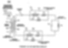

So if the cell has too much capacitive reactance and not enough inductive reactance, introducing the resitive element first slows down the capacitive reactance by presenting resistance to the series circuit first because charge always takes the shortest path.
If there is not enough capacitive reactance then you place the resistance at the farest point causing the capacitive reactance in the series circuit to bottleneck.
So you either cut it off short or you bottleneck it at the far point. Emmm
So the summarise this in simple terms we can either compress or stretch the reactances by the application of resistance at either the front or the back of the cell.
The VIC has evenly distributed inductance and capacitance within its windings, when stan creates an inductance field from one coil that opposes the inductance field of another then the capacitance and inductance are no longer distributed as before because we have a voltage take over situation
so again I will emphasize that it has nothing to do with normal inductance but it's electrostatic inductance which deals with cancelled or opposing magnetic fields.
You are impedance matching static charges rather than current induced voltages.
Therefore it is purely resistance to the static charge not the current i.e no electron movement in the wires so the reactive part of the cell is not inductive, the two boxes around the chokes in his schematic show cancelled inductance.
That is why on the schematic I posted above belonging to stan he only shows a capacitive and resistive element to the cell, the inductance is trapped in the VIC.
He is telling us therefore to match the VIC's resistive value to the cell's resistive value and that it can be obtained by moving closer or further away from a short circuit or a dead short.
So the question should be is what happens to a static charge when inductance is not present in the VIC if you introduce a dead short where the cell should be?
Ed Leedskalin has already found this out, it circulates indefinately, just keeps going around and around.
If you let the charge do this THEN introduce a capacitive region into the series circuit then the cap will only have a Q factor as the resistance will allow, so as the resistance decreases the Q factor of the cell increases.
But we have to be carefull because a dead short presents a loop and even though you had a resistive match at a particular frequency (impedance match) the primary,
because of the cancelled inductance field in the VIC see's no load impedance and the voltage will rise expotentially and not in a linear fashion.
Therefore a loop presents as much danger as a open ended mismatched line in that respect.
So for tuning tubes you would need to set off with low voltage into the VIC at first and establish the Q factor of the cell versus its static resistance and the only way you can provide static resistance is a percentage to a dead short not an ohmic value.
The only way you can create a percentage of a dead short where there is no current in the circuit is dielectric value.
Therefore your cell has two purposes, it presents a Q factor in capacitive reactance and it presents a resistive dielectric property that matches but definately not an inductive one.
The cell has no inductance, it has no magnetic fields, no currents, no ohmic values or any other value associated with current,
placing a normal electrical resistor anywhere after the VIC or in any of the cell's apparatus will be as much use as building a fire barrier out of chocolate. All electrostatic charges where current is inhibited will totally ignoreany form of resistance.
We are dealing with a pure electric field that only cares how much of itself it can fit into a space in time and how far it is away from its own ass,
because the closer it gets to its own ass is the only way you will ever dictate where its going and how fast it gets there. Its own ass can pull it places, its own ass can push it places and its own ass can balance it.
So lets think about this gents for a minute.
The voltage cares not about a resistor is as far as how fast it gets through it, it just cares how much of itself it can occupy in the resistor in the time frame its been given before it meets it own ass and gets chased away again.
In a capacitor the voltage cares not about linear resistance, it only cares how much of itself and its own ass it can fit on both sides of a plate before its own ass chases it away again - or it chases its own ass.
We have a VIC that is full of voltage that doesn't give too hoots about anything linear, it only cares how much of itself can fit into something before it see's it's own ass chase it away.
Your cell and your VIC,
it doesn't matter how big the coils are compared to the Cell or vice versa, it has absolutely nothing to do with it,
what matters is how much voltage there is trying to occupy spaces and how fast it tries to chase its own ass.
There are no impedance matching devices, there is only voltage trying to occupy space being chased away by itself and thats why Ronnie could match a spark plug to his VIC.
Therefore I would agree with scientists who have always said that voltage is not a linear function but rather a spatial one and it is only current that enforces a linear fuction on a charge.
Where there is no linear current the charge is spatial and its fuction is that it occupies a given area in a totally none linear way.
So what are the wires doing then if they are not responsible for a linear voltage charge? The answer is that they simply tell a voltage charge where its ass is and nothing else.
The way that voltage gets from one place to another is not through the wire, it gets there through quantum entanglement.
Nav, the last few posts you have made in this thread make a lot of sense to me and I encourage you to continue your thoughts with Ronnie's permission.
When I started looking at Ken Wheeler's "Uncovering the Missing Secrets to Magnetism", he mentioned electricity being a hybrid of dielectricity and magnetism. I'm pretty certain that information came from Eric Dollard who has studied these things extensively and has the grey hair to prove it.
If I'm not mistaken, the direction you are leading to is that the VIC device is a mechanism to filter the magnetic component (Amperage) from the electrical signal which initiates the process. What we get in the end, in between the plates of the WFC is pure dielectricity which acts directly on the water molecules in a way science is yet to publicly release. I have no doubt there are labs that fully understand this process. Labs that will not under any circumstances reveal what they know to the general public. It is therefore our task to make these discoveries ourselves. Call it research or to search again.
Ronnie has stated the phenomena of the VIC and WFC is actually quite simple and in the coming days it may be revealed how simple this actually is. At the moment we can speculate and/or share our speculations. One or two may be proven correct and others proven wrong. Whatever the outcome, it is my hope we brush off our indifferences and become familiar with the truth however crazy it appears to be. We are at the mercy of our creator to think as we chose and be guided by our intuition. Brace yourself as we enter the unknown, for it may offer up the keys to many locked doors we never knew existed.
God speed everyone. The truth will set you free.
M@
you being up some good points.
Many of us have wondered about the capacitance of the chokes. The aluminum enclosures the chokes are in actually has a large effect on capacitance but it's a capacitance of a different kind.
In radio circuits there is a phenemenon known as choke self resonance.....This is not a resonance between the choke inductance and is own capacitance but a resonance between the choke inductance and it's capacitance to a nearby object....When this resonance occurs the coil forms two series L networks. This causes the voltages at certain points along the chokes to be magnified just as it would in a series LC circuit.
The other thing to consider about the coil capacitance is that it can cause amplitude modulation. If you look at Ronnie's scope shot across his cell you'll see an Amplitude modulated waveform.....Years ago I did a Multisim VIC simulation where I accounted for choke capacitance and other parasitic elements, to my suprise I got an Amplitude modulated waveform across the cell.
Tesla and his equasions are relevant to us and he was the first person in history to prove that in a cancelled magnetic field, a voltage field is not affected in any way and he proved that voltage is not a linear function but a spatial one and that it can get from one place to another at many times the speed of light which he was totally ignored and called a lunatic, but now things are changing because they have found out that if you get a pair of entangled electrons or photons which have equal and opposite charge and you twist one photon then the other will react instantaneously even if one is at one side of the Universe and one is at the other. This is Quantum entanglement. Now imagine of Tesla and Stan are doing the same thing, they create one charge potential and the opposite charge potential happens instantaneously and the only function of the linear wire to to tell one charge where the other is because the air we breath isn't any use for such a function.
The things i've been talking about for months are the conditions that happen in a circuit where there are no magnetic fields to interfere with voltage fields and there dielectric properties. When we talk about impedance, we are usually talking about a function of current and voltage so that capacitive and inductive reactances must be equalled but in this case there is no inductive function only resistance to spacial occupation or in simple terms how much voltage you can ram in anything conductive in a given time period.
https://en.wikipedia.org/wiki/Exponential_function
Most of stan's formula's are based on the expotential matrix where the potential differences across networks are a function of voltage and time but not current and time. But this is the most difficult part to understand: How can an electronics circuit which has a function of voltage and time not have any form of linear function?
The answer lies in what is a volt without current? The answer is a potential difference between two charges and you cannot transport a potential difference down a conductor.
For example, little Johnny can throw a stone 5 yards and little Harry can throw a stone 3 yards. The difference between Harry and Johnny is 2 yards. But what is the 2 yards? What can we do with the 2 yards? The energy of Johnny and Harry can be added together to give a physical energy level but the difference between them is an imaginary difference of potential. Well the difference between the VIC and the cell in the capacitance figures is exactly the same as the 2 yards between Harry and Johnny. You cannot transport an imaginary difference between one potential and another down a wire.

A little experimenting with MultiSIM Blue v.14 (you can download it free at Mouser.com).
I haven't added the resistance for each cell, but the resistance of the coil windings is set in the inductors as well as the core dimensions. This design is with two separate cores driving six 6" plate cells.
At the moment the sim blows up--can't converge for some silly reason. Maybe MultiSIM detects Stan Meyer circuits and does that automatically, wouldn't surprise me. If anyone would like to try and get it working, then add the additional parameters, that would sure be cool. I'd like to see the sim run with some sort of frequency sweep if anyone can make the adjustments.
The purpose of this isn't to demonstrate a fully functioning VIC unit. I'm only using it as a reference for comparing simulated components against real components to learn how closely the approximations are and where I might find the transition points. Also with a sim it's easy to probe around looking for things you might not be able to with real test equipment.
VIC.zip - 85.5 kB
use LTSpice instead of Multisim. It´s also free and coils can be coupled. It also has a transformer model.
Matt, try this then start changing frquencies and cap values. On this particular one the cap burns out after 5 minutes.


I have found that in every coil there exists a certain relation between its self-induction and capacity that permits a current of a given frequency and potential to pass through it with no other opposition than that of ohmic resistance, or, in other words, as though it possessed no self-induction.
I have a strong feeling Stan put Dr. Tesla's observation into practice with the VIC. Which is why it is so important to consider both ohmic resistance as well as impedance when tuning this device.
Impedance Must be a HUGE deal or there would not be a 220 Ohm resistor on the primary.
Or suppose the primary was exactly the value you wanted, then there would be no need for the resistor.
This can only be there to match the impedance.
The primary impedance must be matched yes, but to what is the question. Before you can answer that, you must ask why.
You also need to take into consideration what the impedance is during the pulse, not just when the pulse is off.
In my opinion the resistor is not making the match, but probably i am wrong.
If resistor is lowering a bit of primary impedance, there will be a little load on the source and will not be available on the secondary.
What matters (in my opinion) is the impedance ratio from source to the load. the difference made by this resistor is negligible, since that will not effect on secondary.
One of my big question is about the diode in paralell with primary... was it really on the Meyer VIC? When I put that my amps goes up and secondary voltage drops to almost nothing (Yes I got the diode in right polarity).
X-Blade the diode you may be looking for across the primary may very well be on the Vic Card. Check it out!
Thank you Ronnie. I found it.
It is connected on 6 and 7 pins of the edge connector pcb tracks.

BTW, winding these big coils guided by hand is soooo slooooooow....
144 turns per layer and almost 45 minutes to do it on the first one.
I hope I live long enough to finish. If I'm unable to speed things up at all, that's like 37+ hours of constant winding. Dear lord, what have I got myself into...?
its sounds like you might be doing it the hard way poor guy! have you got an old sewing machine you can modify?
here is my one....with a 13mm chuck and some bushing ect. it takes me around a 2 hours per chock.
http://app.hydrofuel.ca/viewtopic.php?f=7&t=31&start=430
We all start exercising our patients to do with job. lol
On a drill press!
You are dedicated....Do you have a way to count the turns?
If not get a reed switch and solder it to a cheap ebay pedometer....That's what I did, Makes things a little easier. I wind them on my mini lathe which works ok.
I wanted to buy a cnc winder like Russ has but they're 1500 bucks!
take some time and do it... use the 4th motor to run the shaft and the other axes to move left and right...
I went and got one of my cells that I use and here are the measurements.... outer tube inner Dia=.648 inner rod Dia=.5 Gap=.074
He must have not got his information right on that website. Sorry I gave you that link to misleading information. I'm still a little puzzled about the balance part you posted. Please explain!

Do we have ideas how to accurate measure low AC current/high voltage (range 1 - 30mA, 1-50kHz) with a sense resistor (low,high side?) or a sense coil?
I can't find a decent active differential instrumentation amplifier below 100kHz with scope connector signal output.
Meyer states if we adjust our B+,B- voltages we restrict current. But I think the coils won't have exact current 90 deg out of phase (LEICIE) if we also have voltage 180 deg out of phase...hmmm Leakage!! Perhaps both currents wont be equal at all?
We need some low cost DIY toy (differential current sense instrumentation amplifier) to measure the B+,B- currents...2 or 3 channels...
https://www.tindie.com/products/LDLabdevice/accurate-high-bandwidth-currente-probe-100ma/ $$$
breakout-pcb?
devkits?
http://www.analog.com/media/en/technical-documentation/data-sheets/AD8418.pdf
https://wiki.analog.com/resources/eval/ad8418-evalz
http://cds.linear.com/docs/en/application-note/an105fa.pdf
Anyone?
temp notes
U shape ferrite core of UY1658 machine,
hight watt
uly 14, 2013 Test Results...
3 Guys walk into a room with a tube of water... Stop me if you heard this one before :-)
So, we have a single test cell, as documented all over the site. Gps graciously made one for me, and his was there also. I luckily got Version 2 which is more stable. See the above photo, in a previous post.
The Tube will produce a ton of HHO with 50V @ 1.5A (75Watts) going through it. This is the wide open DC mode as a baseline... Tap water was used.
The Setup:
- Small 3" Tube set inside Delrin/Plastic
- Signal generator, Square Wave
- Optical Isolator
- Power Supply set @ 15.5V (usually pulling <1 Amp)
- Transistor (2n3055) managing the Positive Side power
- Scope Ch2: Input Signal, Input Frequency, and Trigger @ 50%
- Scope Ch1: HV Scope, usually at the cell, but moved for testing
- Transformer (7-9 Turns@Primary : 1770 Turns@Secondary)
- HV Output from the Transformer was verified!
- Common Mode Chokes: 1770 Turns on each, sharing a D core
- Both Chokes/Transformer were using the same cores
- http://www.aliexpress.com/item/large-watt-U-shape-transformer-ferrite-core-UY1660-machines-equipments-10pairs-lot/493680068.html
- Primary was 16 Guage Magnet wire Double Coated
- Secondary was 30 Gauage Magnet wire Double Coated (triple is needed)
- A Large Chasis Mount Diode
So, signal generator -> opto isolator, this drives the transistor.
Power -> Transistor -> Primary Coil
Secondary -> + to Diode -> +Choke, - to -Choke/Probe Ground [inputs]
Choke Outputs -> Cell and +Probe
=== now, the primary and secondary windings changed during our tests,
as we were trying to increase the voltage. We also played with reversing the direction of the NEGATIVE CHOKE (swapping which wire was IN vs. OUT)
I will try to indicated EVERYTHING in each TEST case that we ran.
===
Misc Tests:
Straight DC:
Made Tons of gas @ 15Watts (No circuitry)
Circuit w/o chokes:
We don't get the High Voltage
Circuit w/chokes (Baseline, 10 Windings on Primary):
High Voltage, Lit the bulb. Bulb lighting drew only .01 to .02 additional amps, and in some cases seemed to REDUCE the amps being drawn by the same amount.
At least 700V were needed to light the bulb TOUCHED to the water. A bit more to light the bulb for just being NEAR (but very parallel) to the water. ** I plan to strap one to my tube!!! This light can be used in lieu of HV probes. Brighter light indicates HIGHER voltage) **
Voltage was around 1.5KV
Res Frequency: ~18KHz
** NOTE: Baseline X: -> We started with baseline, and made only the changes indicated in the Parenthesis!
Baseline B: (We removed the NEGATIVE CHOKE)
We lost resonance, could not get it back.
Baseline C: (We added a second Cell)
Resonance was still there at the SAME FREQUENCY. ERGO, The resonance on the first half is NOT LC resonance!! This is more like TL (Transformer, Inductor). The Resonance REQUIRES the inductor/Transformer to be synchronized...
The water in the second cell was CHARGED and would LIGHT the bulb the same way.
Baseline D: (we swapped the Negative Choke Wires)
The Frequency was Cut in 1/2, The voltage BASICALLY doubled
This was cool. Lots of Noise/Inteference. The scope had a tough time because some of the impulses were beyond the 4KV of the screen
Voltage was OFF the charts without the bulb there. Anything over 4KV would be beyond the scopes ability to measure. And we were getting a pattern that would give us more than that and settle down, and then go above that. We have no idea if we had 4.001KV or 40KV. But when we put the light bulb in the water, the voltage came down a bit, and we could measure and tune it like that (Hey, when all you have is a hammer <g>)...
So, we were now at ~8.92KHz and 2.34KV
NOTE: ** At this point, I realized we were measuring Frequency on Ch1, so after this, I choose to measure frequency on Ch2...
NEXT: We played with Undoing and redoing the connections to validate we got the same results... All was fine.
NEXT: We discussed what we should do next. GPS suggested we try to get a higher Voltage. That when he had this working, the voltage SEEMED higher, the light was brighter, and just bringing it PERPINDICULAR to the water tube would light it up to your hand... Ours barely got brighter...
NEXT: We removed a couple of turns from the primary with no effect, and rewound a new primary with 11 Turns (as our baseline).
Baseline E: (2483 Turns with a center tap on Secondary)
We measured INDUCTANCE (air core) @ 18.97mh and 63.2mh
NOTE: We should measure it with the core as well, this is used to test for the short we know we will ultimately get when we goof...
We were at 9KHz - 10Khz... We were PULLING fewer Amps (0.73A@15.6V)
We got 1.88KV (Keep in mind, we undid the reverse wiring)
We measured Voltage out of the secondary it was slightly HIGHER than the voltage out of the Cell (I did not write it down).
Baseline E+F: (We swapped negative choke on Baseline E)
We got 4.8-5Khz resonance
Power: .64-.72A @ 15.6V
Result: 1.80KV
NOTE: We started blowing fuses and cooked our secondary...
We re-wound it to 1770 Turns to match the Chokes. [We, in this sentence means that Rav and I were moral support as Gps whipped out the coil spinner and we watched slacked-jaw <g>]
Baseline G: (New 1770 Turn Secondary)
1AMP Fuses @ 250V were used on the INPUT to the Transformer.
Below 1AMP and we would burn them up... 1AMP would glow if we went above it for a bit. 750mA fuse glowed the whole time, we pulled it.
NOTE: We learned that the ground goes BEFORE the choke, just like Meyers had it. The ground on the scope probe was being used to go to ground. WITHOUT THIS ground in place, the bulb was not lighting...
We got: 18-19Khz resonance
Power: .95A/15.6V
Result: 1.44KV (left alone, rose to 1.52KV)
==
At this point, I had not prepared for all the notes I was taking, and we were stuck asking about the next tests we should run. So, we switched to a different signal generator (digital display, and duty cycle control).
==
We cut the Duty cycle down to 20% and still had resonance and were able to light the tube. Interesting.
TODO: Determine the Approximate Voltage required to separate water into HHO using only dielectric breakdown from Extreme High Voltages.
My apologies to Gps and Rav for the many things I am sure I missed. We were there ALL DAY, and Gps served up some great steaks/potatoes, etc. He also gave me a couple of other things he had available, for which I am eternally grateful. Good People... Both of them.
###
In closing. We came, we saw, and we moved the ball forward on the field. Holding that light with such a simple setup was AMAZING.
Now, our thought processes are:
1) GPS will rebuild his Lawton device to see if he can get closer
2) GPS will rewind some coils (since giving me his)
3) Rav will research voltages required for dielectric breakdown
4) Rav will continue CAD Modeling the final unit
5) I will research dielectric breakdown and try some calculations
6) I will use the information from the Transformer/Chokes to reverse engineer some of the calculations for Resonance...
7) I will also try to conjure up HELPFUL explanations for what might be going on, in order to move the state of the art forward
8) I am going to make sure we DOCUMENT and SHARE what we find, so GPS and Rav do not have to spend the time doing it, since they have given so much already...
9) Rav is subconsciously going to realize that he wants to test removing the signal generator, and wants to drive the 2n3055 with a feedback loop from the primary side of the transformer, like a flyback, and SEE if this creates a self tuned system with the SAME frequency we get to... (He was trying to suggest something like this all day, and it just now dawned on me what he was trying to say, LMAO. This is why I like writing things up, it allows me to relive them, and gain even more insight).
Anyone wanting to chip in and move the conversation forward is welcome to.
We have clearly shown that the RESONANCE is NOT about the capacitor, but about the inductor/transformer, and that is KEY.
Now, maybe the difficulty and the magic is that it becomes a Double Resonant system, in order to produce HHO. That we don't know. But the diode in the design makes me doubt it. The diode inhibits a normal tank circuit operation, and the WFC does not act like a good Capacitor.
So, MAYBE we need to drive the Voltage high enough so we get VOLTAGE based separation of water into HHO (and potentially Ozone(O3) and H). Much like an AIR Ionizer works. We want to Ionize water a bit? We want a cascading dielectric breakdown to start, and when it attempts to draw current, it is CHOKED from being able to do so, and instead, the high voltage field is maintained, and the cascading effect is forced to happen again and again... Just my thoughts at this point.
Before anyone asks. We saw very little HHO production during these tests. But that is not the current goal. We want to create an environment similar to what Stan did, and what GPS had created 3yrs ago. Not normal hydrolysis like we have all been playing with for some time.
Kirk Out!
PS: For a laugh read the first line and the PS of my "Introduction Post" :-)Oh, and one other thing I forgot to mention...
Usually when I would power an Inductor + Cell... I would find MULTIPLE Resonant Frequencies at INTERVALS. So, if I could get a 13K signal to work, at 26K I would lock on as well. And this makes some sense.
Well, with this setup, we did not find that to be true. When 9KHz was the bomb, 18KHz was not even close, and sometimes did not show even a solid pattern. And we tried LOWER as well. Very interesting.
Mastering the VIC
I'm a paragraph. Click here to you made a promise and can´t give more information about problem solving details - I understand.
here comes what I don´t understand:
what voltage across the cell (between points D and E) did you reach and
what results and effects in detail did you get according to gas production?your own text and edit me. It's easy.
.jpg)
Interesting relation between two surface areas of the wfc and the chokes? Don't know if this a coincidence, I think not :huh:

nteresting numbers
Where did you find them?
Coils data are from Dynodon excell sheet, I did the surface area calculation and I was looking for a factor why the chokes are not equal??
There must be more with the secondary and maybe the primary and pickup??
an you explain your calculation on your chart. why did you divide them?
also i have some thoughts on this and it boils down to the capacitance of the coils VS the capacitance of each Cell Plate... Capacitance should be calculated according to the surface area. yes or no?
if yes,
so that means each plate has a different capacitance and the " chokes" might complicate for that?
maybe the compensation is in capacitance of the "chokes" ? try taking don's values on the capacitance measurements and doing the same thing as you did on the inductance...
Description
Well, the two surface areas of the electrodes are not equal. The factor between those is what I noticed in why the voltages are not equal from the chokes to the two plates... Not sure yet how to solve this in capacitance, frequencies etc.
The same or almost the same factor is between the choke coils?? One choke, has more voltage to compensate the other...equal but opposite voltage is what you want to see at the plates, or not? If yes, then there is no current leakage out of the wfc?
Edit: The capacitance data I have not done... with this factor, yet.
Looks like its the inverse of the factor. (1/Factor)
here is some nice calculators that may help.
http://www.ajdesigner.com/phpcapacitor/capacitance_equation_v.php

so basically, the Q+ and the Q- need to be equal voltages.
Not exactly true as we have larger surface are on the cathode and to make more gas we need slightly more positive charge in the cell to make gas which is the actual goal here
looking to calculate the voltage difference VIA the surface area...
if Q+ is the inner surface area and Q- is the outer surface area
if Q+ is at 100V then to get 100V @ Q- we would need more voltage potential. in the L2 choke... ?? yes?
lets look,
L2 seems to be smaller, so, we would need to say that the Q's are switched.
Q+ is the outer and Q- is the inner
lets say we want to know the stored energy in in inductor.
L1 at 64.32mH and 500Ma we have 0.0080400000J
L2 at 76.32mH and 500Ma we have 0.0095000000J
dived the J and we have :
1.1815920398009950248756218905473
this matches the same numbers as the area of Q+ / Q-.
1.1053217133320971629890598924532
as you showed on core should be even closer...
Looks like the capacitance is the inverse of the factor. (1/Factor). Obvious. (Inductance/capacitance)
(1/1.1053) 0.9047
Q+ is the outer and Q- the inner.
It's a asymmetrical capacitor so these charges are unequal, not Q1 = - Q2. You get a voltage drop.
do have a simple. qustion,
to compensate for this could we not connect 2 cells where there outter-inner-inner-outter and have the same capacitance on each plate?
can you recalculate the surface area of the "exposed area" of the inner tube?
the derlin caps play a roll in the area.
Total voltage is divided by the number of capacitors, hmm maybe thats why stan used 10 to create balance? But...
Voltage drop is on the inner electrode, so this is connected to the next outer electrode. So less Q?
Cant answer that for sure?according to the photos. its inner-outer 1-10 so I'm not sure there.
Color the surface area what you want to know extra in red. I do new calculation tomorrow..basically the parts covered in derlin..
something like this :

Did the math a while back and found the difference in surface area of the electrodes is 1:1.18, Also the choke inductances L1:L2 have nearly the same ratio.
But having the cells connected as they are might change the requirement(s), if there are any?
Edit:attachment
Surface areas of the inner electrode configuration

Non Meyers Next gen steps
Back EMF BEMF
Have been looking at the VIC very carefully based in large part on diagrams in this thread and my lately re-kindled collaboration with Russ. In revisiting many long-held assumptions, the VIC schematic is starting to look like the attached drawing.
Note:
(1) The primary can still communicate flux to the secondary if the cores are arranged in the manner shown higher up in the thread (ie., with two rectangular cores set very close to each other. I think that proximity between the cores might even serve as a fine tuning point for striking some flux flow balance; though I haven't yet tested this notion.)
(2) The frequency values indicated are arbitrary and should be considered as either manually or dynamically adjusted.
(3) Of course, protect your pulse driver from BEMF originating from the primary; for the sake of brevity, I excluded this type of protection in the schematic.
(4) Will need a "blocking diode" with a higher voltage rating then a 1N4007 (beyond just a few bench tests).
What was your exact configuration that reached 40 KV over the cell?
What measurement tools did you use to measure that high voltage?
The success I have had to date has been by focusing on driving BEMF into the cell, which at resonance is often a full order of magnitude higher then the forward EMF.
Therefore, I've been working to stoke the BEMF as high as possible and these are the 40KV voltages I am referring to. I think the way we are considering the VIC in this thread (where we are allowing, at resonance, the EMF and BEMF to play out on both sides of the cell)
could make all the difference in terms of getting the amplitudes and electrostatic winching forces "felt" by the cell (and water) to much higher levels then I've seen before.
I think it could make all the difference, taking us from the light EPP based gas production I am now seeing (eg. https://www.youtube.com/watch?v=5kPcZ7fZTS8#ws) to significantly greater gas production; the kind of production we need to move this work forward to a meaningful next level.
agree. To harvest some of the BEMF the primary diode configuration plays an important role. How did you configure that diode? Did you use a diode at all?
I agree. To harvest some of the BEMF the primary diode configuration plays an important role. How did you configure that diode? Did you use a diode at all?
I use a cathode-facing diode on the Vdd side of L1. I do this with the idea of allowing BEMF to pass from the other side of the circuit while stopping forward EMF from progressing its way back around.


