
GO Faster Go Further
Established since 2001

Hydrogen Hot Rodding™ ©

Secure Supplies Group

Modern Water Fuel Circuits
THE STUDENTS OF HYDROGEN HOT RODS
I decided to put this basic entry version circuit at top of this page as most of you all need to fully understand this one first ,
i know most of you will say "God so basic "but yes it is ,
Keep this version in mind at all times before moving on to the 2020 Circuits.
Remember no salts no electrolyete only distilled water ,
BESURE to put a Gap in your transformer /Choke
as it makes more capacitience to cell.
We can all laugh but remember as of May 2020 many of the so called Best in world hydrogen companies are still stupidly using electrolysis and have
no idea of VOLTROLYSIS
Simply put take their business away from them immediatley.
Febuary 26, 2013
Here is Daniel's power stage that he used in trials and tests with values and everything.
Sorry for the delay in uploading the scheme but it is not easy to design and upload something that really works well, this one I am uploading works quite well with power supplies from 15 to 350VDC The coupling with the pulse generator is by a driver for the TLP 250 mosfet, it is like an optocoupler but improved. It works well up to 25Khz. I use an IRFPC60 N-channel mosfet that supports up to 600v but if they are going to feed it with less than 200vcc an IRFP250 or 260 is fine.
Features:
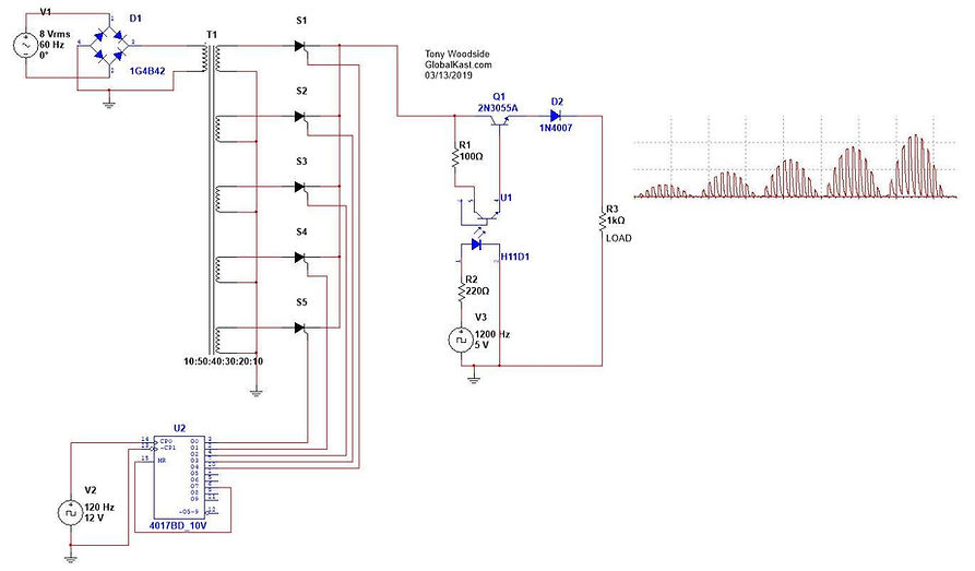
STANS REFERENCE CIRCUIT 9XB
Power: 15 vdc to 350 vdc.
Maximum current: 4A
Maximum frequency: 25khz
Input: TTL signal (5vcc) 20ma max.
NOTE BE SURE TO SMALL GAP the E52 2000 Perm Core
Cold Process
No electrolyte

Voltrolysis Stanley A Meyer

Many people are shocked when they realize they Stanley A Meyer Systems and methods work as stated, they are also often shocked to learn water is fuel. What often shocks them most is Stan's systems and circuits are extremely wide spread in use and being taught built and put in place around the world. This Initial Circuit below is " School Girl Circuit" if a School girl can build this and have water fuel so can you . ENJOY ( no electrolytes use distilled water.)


HYDROGEN HOT RODS
GO Faster Go Further
Stan Meyer's 8XA - 90 degree control:
•28 May 2013 ( attention is in the detail of what does 90' degrees mean.?" LMD)


Electrical Polarisation Process - Water electrolysis
•8 Mar 2014


8XA Bifilar inductor
•9 Mar 2014
Stan Meyer's 8XA - Amazing Step Charge !!!!!
•29 May 2013 Let me take this moment to remind you to join as a Builder member or Make a Donation to help us keep this information here and growing.
Remember to give more than you take from this website please. Thanks Dan


Stan Meyer's 8XA circuit has one serious drawback - if network frequency (110 Volts / 60 Hz) is change, "Step Charge" settings too changing.
As you know, the network frequency is vary! Stan Meyer's 8XA circuit without 4-Diode Bridge Rectifier. The circuit work like Stan Meyer's VIC - "Half-wave rectification":
http://en.wikipedia.org/wiki/Rectifier
"Gated" Generator is tuned to 51 Hz ! (Supply frequency 50 Hz / 220 Volts) My modifying 8XA circuit with Half-wave rectification and 180 degree control:
(Zener Diode is added)
High Voltage, Low Current - Water Conductivity
•30 Jul 2016

Stan Meyer's 8XA
•5 May 2013

9XB Merged with SCR 2 in 1
•04 Sept 2021 We have managed to reduce the wiring more and label it better for fast installs and use.
If you would like to order this board $80 for pcb we provide bom and or
You can order from us Fully Assembled $120
https://www.nikola-truck.com/product-page/9xd-9xb-scr-3-in-1-pcb-only

Stanley Meyer's 8XA Hydrogen Fracturing Process
•04 October 2022
Input: 220 Volts / 50 Hz Half-wave unipolar frequency next the Graetz -
100 Hz Gate frequency to the Optocoupler`s input
- 51Hz (or 49 Hz) / 50% Duty-cycle Anode Inductor C1
- 400 turns Cathode Inductor C2
- 404 turns* How to "fine tune" the Cathode inductor "L2":
If "L2" have exactly 400 turns /like L1/
- the Waveform is "most Positive":
If "L2" have 410 turns /10 turns more/ - the Waveform is "non symmetrical" - the Negative voltage outweighs the Positive voltage:
https://www.nikola-truck.com/product-page/9xd-9xb-scr-3-in-1-pcb-only

9XAM
Now a Merged Circuit is released to public with Transistor to simplify assembly of the voltrolysis training circuit which has 9xs 2 9xbs providing power a gate and a over layed
5 khz signal on 5 khz
If you not already a Patreon of Secure Supplies please join here to ensure we continue sharing the latest items . https://www.patreon.com/securesupplies

Water cell with Isolated surface... Is this possible?
•12 Feb 2015 Toroidal transformer - FERROCORE T41X15X27 As you see, about 600 Volts is absolute minimum for Water dissociation, if Water Cells is covered with insulation layers! Now i search more effective insulation method.


Stan Meyer's Electron Extraction Circuit- Training Version
•13 May 2013

8XA circuit with High Power SCR
•3 Jun 2013 Stan Meyer's 8XA circuit has one serious drawback - if network frequency (110 Volts / 60 Hz) is change, "Step Charge" settings too changing. As you know, the network frequency is vary! This can cause heat and changing results
Generator is created with LM 566 - VCO (Voltage Controlled Oscillator) For prevent overheating resistors, Ultra High Power SCR is controlled by other Low Power SCR - Darling ton circuit

HHO Ultra Power Driver
•16 Jun 2013 This is my new circuit! "Step Charge" time is constant. Output Driver power is over 30000 Watts - over, over, over... than need!
"Frequency Adjust" - tune "Step Charge" time. "Maximum Voltage Adjust" - tune maximal voltage limit. "Positive Ramp Offset Adjust" - coordinate triangle waveform to optocoupler.
"Minimum Voltage Adjust" - tune the minimum voltage at which water molecule is Breakdown - "Water Breakdown Point" "Step Charge" vary between Voltage "Water Breakdown Point" and "Maximal Voltage"!

Ultra short pulse water electrolysis
16 Oct 2013
Stanley Meyer's Water Fuel Cell Resonant Condition with use TAP WATER Professor M. Kanarev - "GENERATORS OF GLOBAL (CLEAN) ENERGY" http://guns.connect.fi/innoplaza/ener... BACKUP DOCUMENT HERE
"A novel method of hydrogen generation by water electrolysis using an ultra-short-pulse power supply" http://www.tuks.nl/pdf/Reference_Mate... BACKUP DOCUMENT HERE also see Lex Banki Nano pulser


Water electrolysis
•22 Feb 2014


How to Measure the Capacitance of Water Cell
•10 Sep 2017


How to measure Self Resonant Frequency of the
Stanley A Meyer Water Fuel Cell
•23 Oct 2016

How to De Ice Water Cell
•17 Mar 2015
Remember we want to stay under 25 C so we keep nano bubbles in the water


RESONANCE
•17 Mar 2015


Andrija Puharich`s Circuit diagram
•6 May 2017
Stanley and Stephen Meyer based some of their circuit thoughts on Andrija Puharich`s
and Nikola Tesla's circuit Works.
You can continue study on these on the START HERE Test Cell Pages which Proves
Stanley Meyers Systems work and that he told the truth to save mankind.


Stanley Meyer`s RESONANCE Water Electrolysis - DEMONSTRATION
H Bridge 25 Apr 2020

Stanley Meyer`s RESONANCE Impedence Matching Circuit A Voltage Doubler with Inductors. 21 Mar 2020

Exmaple
1 Set per Phase Leg total 3 phase Volternator
6 Cells
Mistakes Corrected in Stephen Meyer`s RESONANCE Impedence Matching Circuit A Voltage Doubler with Inductors 21 Mar 2020


Now, the three coils, placed on "common ferrite core", have equal number of turns (the "3-filar coil" is "not tuned"), only C2, is connected on "opposite direction".
The Osciloscope probe is connected between the "Test point T1" (Input) and "Test point T2" (Ground).
Very important: To the "Impedance matching circuit" is applying "only" Sinusoidal signal, with fixed frequency about 500 Hz. The "ringing" Resonant signal at 13,5 kHz, is "forming" from the Resonance inductors.
Important note: 1981 schematic of phase 4 voltage intensifier circuit this tells me it took 10 years to find the winding recipe for chokes:
Stephen Meyer`s Patent US 2005/0246059 A1:
My Circuit diagram:
My 3-filar coil:
"Output signal" to the Water Fuel Cell:
The "Ringing" Resonant signal (the Inductors "not tuned"):
"Identical" Stanley Meyer's circuit diagrams, with "third electrode" added:


Vital Knowledge
The Following videos are vital to learn and understand as Stephen Meyer made all Stan's Circuits he was a Well Trained Radar operator.
God Speed God Bless
8XA - Car Alternator's RPM - 10000 min-1
•16 Jul 2016


Resonance "Step-Charge" with Car Ignition Coil and WFC with "Insulated Surfaces"
•16 Feb 2015

Stanley Meyer`s RESONANCE Water Electrolysis - DEMONSTRATION
H Bridge 25 Apr 2020
This circuit has two pots, one for adjusting the primary coil voltage amplitude and another for adjusting the pulse voltage amplitude of the pulsing during the 'Gate' time.
There are four options for driving the primary coil.
1. Gate time high-Current flows through primary coil during gate time
2. Gate time low-No current flowing through primary coil during gate time
3. Variable pulse voltage amplitude during gate time (via P2)
4. Continuous pulse frequency
Both high (resonant) and low (gate) frequencies are provided by a FeelTech function generator which provides independent frequency, duty cycle, and sweep functions. The drive circuit, function generator and VIC coil are all powered by a Ryobi 18V battery and a programmable power supply as seen in previous videos. Here you can get the Multisim and image file/schematic

Note this file got damaged i have tried to clean it up from screen shots if any finds original please email me and I swap it out to be clearer for builders. danieldonatelli1@gmail.com

Stan Meyer's Electrolysis method ( Circuit below is only part of box)
The is the foundation of the Vic Matrix.
•14 Mar 2014

VIC Drive Circuit April 2020
•29 Apr 2020

This circuit has two pots, one for adjusting the primary coil voltage amplitude and another for adjusting the pulse voltage amplitude of the pulsing during the 'Gate' time.
There are four options for driving the primary coil.
1. Gate time high-Current flows through primary coil during gate time
2. Gate time low-No current flowing through primary coil during gate time
3. Variable pulse voltage amplitude during gate time (via P2)
4. Continuous pulse frequency
Both high (resonant) and low (gate) frequencies are provided by a FeelTech function generator which provides independent frequency, duty cycle, and sweep functions. The drive circuit, function generator and VIC coil are all powered by a Ryobi 18V battery and a programmable power supply as seen in previous videos. Here you can get the Multisim and image file/schematic
BradK-Hybrid VIC Driver-April 2020.ms14 - 211.53 kB, downloaded 6 times.
Bifilar Inductors
• 2016

Meyer's VIC-Resonance
•7 Feb 2016

Stanley Meyer's BIG BOBBIN
•12 Feb 2016
What is very interesting in this practical solution?
1. Because here is no opposite-connected inductors,
it is not necessary to "adjust accurately" the Resonant frequency.
BIG BOBBIN not have "Resonant Scanning Circuit", not have "Pulse Pickup coil"
like at VIC-Transformer. BIG BOBBIN work like standard
"ATX Power supply Pulse Transformer"
and only produce "Step-Charge effect".
2. It seems that gas production is better, when the Voltage on the
cell is in "both directions" - starting with a "Negative voltage"
and ends with a "Positive "voltage", like "Hysteresis Loop Figure"!!!
This is the effect Andrija Puharich named:
"Rotation moment of the proton magnetic moment":
"This sets up a rotation moment of the proton magnetic moment which one can clearly
see on the XY plot of an oscilloscope, as an hysteresis loop figure.
However,
it is noted that this hysteresis loop does not appear in the liquid water sample
until all the parameters of the three components have been adjusted to the
configuration which is the novel basis of this device.
The hysteresis loop gives us a vivid portrayal of the nuclear magnetic
relaxation cycle of the proton in water."

Meyer`s "Dual-Layered Multi-Spool"
•1 Oct 2017
_JPG.jpg)
Step-Charge effect without Bifilar Inductors
•2 Feb 2015


Step-Charge" effect with Bifilar Inductors
•4 Feb 2015
This effect can be created with only one Inductor (e.g. only positive Inductor), but the Waveform is not symmetrical ! The Inductor with the Water capacitor create frequency dependent circuit. Stephen Meyer's Original device work on different way! High-Frequency sinusoidal signal (about 13,5 kHz) is created from rotating car alternator. "Gate" Frequency (about 600 Hz) is formed from Relay controlled switches:
In Patent US4936961A Stanley Meyer present what is a "Resonant charging choke": The overall circuit is characterized as a "resonant charging choke" circuit which is an inductor in series with a capacitor that produces a resonant circuit. [SAMS Modern Dictionary of Electronics, Rudolff Garff, © 1984, Howard W. Sams & Co. (Indianapolis, Ind.), page 859.] Such a resonant charging choke is on each side of the capacitor.

Stephen Meyer`s Signal Replication
•23 Nov 2014


Stephen Meyer`s Waveform replication
•2 Sep 2018
Water Resonance Waveform
•7 Oct 2018
_JPG.jpg)
How The VIC works - Part 1
•27 Nov 2014

Transformer Searcing the Resonant frequency of Water cell
VERSION Vic common core torroid prmary secondary and chokes Transformer and GMS
•9 May 2019 ( this Video was showing the inverted signal from pwm to the switch and pll)
Reference Video put in the Vic Matix Rresonance Tab)
Water Resonance waveform with Bifilar Inductor SYNCHRONIZATION CIRCUIT

Stanley Meyer's VIC Replication
•6 Sep 2014

Water Resonance waveform with VIC - Transformer
•19 Nov 2018

The Bifilar inductor - the most important part of Meyer`s invention
•20 Aug 2018
.png)
Home Made Oscilloscope High-Voltage probe 1000:1
•4 Jun 2016 We have a Page for the Custom Probes HERE

Note 1
We can avoid using many expsensive high voltage measuring tools
and some of the high voltage dangers by measuring the magnetic flux
some magnetic flux meters have volts on them for that reason ,
this allows us the experiementers to have better a safety level and better measuring options with out being directly exposed to High voltage during testng

Opto-Isolator for Oscilloscope probe
•21 May 2017 Ref Andrija Puharich`s Patent US4394230A

Frequency doubling - How to the Resonant inductors work
•24 Aug 2017


_JPG.jpg)


How to VIC Transformer "tune"
•17 Jan 2021VIC
"tune" Formula: Rsec. = (Rc1 + Rc2) / 2
NEW 2021


Stanley Meyer`s Hydrogen Gas Gun
•23 Mar 2013 Note this circuit is using 12 vdc and out cold voltage and using magnets for the polarization it is not ac out
we can also use vic dc with h bridge or electron extraction

Digital control means Tds voltage level control
Using a lm 2917, Here is a circuit made years ago.
The output from the f/v generator pulls down the c/v pin on the 555 adjusting the duty cycle of the 555 gate timer based on engine rpm. (crankshaft sensor) 555 used to simulate.
Builder was counting the pulses, but you do not have to.
An edge trigger off the frequency output can trigger the gating monostable also, eliminating the 4017.


On Demand
Gas Management System
Stanley A Meyer Gas Management System
Replicated with Matrix and Db 37 allowing
-
Auto Water Fill
-
Auto Tune
-
Direct connect to Hydruino (Ardunio ECU)
-
Auto Engine Start once fuel rail pressure reached
-
Automatic cell pressure scaling
-
Parallel Vic Control and sequence firing control
-
Safety Controls
-
Power Module Ready with rails to drive ecu and expansion cards
-
9 Water injector Pwm driver signal into Big round bobbin
-
Auto duty , pwm and amplitude adjust to throttle position.
-
Packed in Box for Distribution
21/08 2020

Ace-high Straight flush

Relay Power Control Modules with staged on off sectioned on off Vic , with wireless remotes and blue tooth.
Mil Spec Compliant
.png)
Replacement for the K7 Laser Accelerator K7
Meyers TPS Board Connect TPS sender Sensor from all cars Bikes to the K11 Digital Control means which slots into the Meyer GMS VIC Matrix Main board. NEWS we have now merged tps k7 and including the k11 digital control means greatly simplifying the connection and build.. to make Gas On demand
•12 th Sept 2021

GMS Matrix Main board now with db 37


KAGF1


Stanley Meyer's VIC - Double Amplitude modulated Resonant Waveform
•13 Nov 2022
The "Resonant frequency" is tuned at: 16,7 kHz
The "GATE frequency" is tuned at: 2,98 kHz (create First Amplitude modulation)
The "Unipolar rectifying" is at: 50 Hz (create Secondary Amplitude modulation)

Parallel 10 Vic


Further Merging of VPS and VTA occuring will post soon.

Main part of the step charging circuit that people have
\ missed. Everybody thinks that step charging is an effect that
happens, but it's not. Voltage doubling is real in each vic but the
Step charging was a forced oscillation. meaning yes we get voltage doubling we get LMD oscillation and cell charging , but in additional we can magnify oscillations with trigger time parallel vics if it sounds like a very powerful fuel on demand maker it is..
THANK YOU HYDROGEN HOT RODDERS
Note August 2020
There are about 40 circuit diagrams to add to this page current and modern working,
Please consider making a Donation if you want to see them
BIG BONUS FOR YOU
Mini Genset waste spark
and CDI TDC Controls
Remember to donate and become a Patreon please.
Click here to get your circuits

Using Audrino and Signal Generators
I was hesitating for several years whether or not to put these pictures and videos amongst Stans work.
The main reason is that while these microcircuits and chip, board and tools are very modern and great they are in fact heavily based on digital operations. In Some Respects we need simple done first and anologue particulary for the PLL. Phase Lock Loop.
SO I ADVISE advise people to Start first with 9XB 9XA and Switches
and EEC First. Master those 1st than try circuit above remembering we have over 11 versions which all work we can use all eleven with out this version which is version 5 and 10 11,
The Advatage with looking at these pictures is not to ignore the above modern circuit but to see what to do after you have built 9XB 9XA and Swtiches and use the Circuits above with EEC and H bridge and back switching eec. First then try the following ones.
If you ignore the advice you will find your self
asking high volt no gas? As many so called all knowing individuals have found out the had way.
You can than look and study the full VIC Matrix , and use the Mini Audrino as daughter board to make a new carry card like Gunther did
handling pulse and gate throttle position sensor and
Consolidate the VIC MATIX onto one board so you have micro controller, filter board and switch.
(Frequency pulse Generator, Digital Control means card, vic card,
Gas feed back card, Gated Pulse Card all on to filter board. )
So Here I show some pictures for what this would start to look like
and also a video of what the very very basic one Gunther did when compared to Stans Vic Matix,
I would suggest buy it to learn it but use the above diagram to advance it do not base on it too much as we need better than the carry board, the switch from Gunther is excellent to start with.
As are many Desk top Signal Generators .
Like Brad Shows in some of his table top tests to driver vic driver or filter board.


Arduino-Stanley-A-Meyer
50% duty cycle pulses and 50% duty cycle gate 2 pots control frequency
and number of pulses in the pulse train
2 different versions of the code for
2 different frequency ranges
1 hz - 500 hz
32 hz - 10 khz
Current Board Order Availability 2020/21
Delivery with in 10 days
==================================
Power Section
==================================
9XD Original from Black
9xd
POWER Control Board GMS MAIN
===================================
PWM SYSTEMS
===================================
8xa
8XA by Tony Woodside
8XA Digital Board V1
9XB Original
9XB
9xa
LED Pulser
VIC Original
Vic Tony Wood Side
Vic Sharky
Vic 5 Matt
===================================
Switches
===================================
SCR
Alternator Board Type 1
8xa 9xb Switch Driver
VIC Transformer Daughter Board
Standalone VIC driver Board
VIC driver Board mini
EEC Electron Extraction
Half Bridge Switch Driver 1 kv
H Bridge Stanley A Meyer back switch
Uni Switch EEC
===================================
Gas Management System
===================================
DB 37 Main Board MAtrix Vic GMS Gas
DB 37 Gas Feedback
DB 37 k11 Digital Control Means
DB 37 K2 Variable Pulse
DB 37 Gated Pulse Frequency
DB 37 Pressure Regulator Circuit
DB 37 Auto Start
DB 37 Safety Bypass Control Card
DB 37 k11 Digital Control Means
K11 Ribbon Piggy Back TPS Interlink to GMS
DB 37 POWER Control Board GMS MAIN
Db 37 Analog voltage card
====================================
Gas Processor
====================================
7 LED Gas Processor
16 LED Gas Processor
14 LED Gas Processor
====================================
Solid Start Controllers
====================================
Steven-Mark TPU Driver Beta V1
EPG Circuit Board Magnetic Pump Style 4 V2
EPG Mechanical Pump Circuit
====================================
ECU EMS
====================================
Speeduino EFI Shield Mega 2560 Pro Rev
Speeduino NO2C-v0.2.2
Hyduino 4.3c (Speeduino+ H2 Gms
Hyduino 4.2 (Speeduino+ H2 Gms
Hyduino 4.4b (Speeduino+ H2 Gms
Mazda Miata 48 pin rev C Speeduino
Hyduino Stim Stimulator circuit board Ms
Hyduino 4.3b (Speeduino+ H2 Gms
The Hyduino (Speeduino+ H2 Gms
=====================================
Legacy Ecu Gms Boards
=====================================
Exhaust Gate Tuning Circuit
Exhaust EGR Gate Control
Safety Card GMS Gas
Taco Board GMS Speed
Steam Resonator
Distributor Card Timing
INjector Card Timing
k7 Digital Accelerator Circuit Board
