
GO Faster Go Further
Established since 2001

Hydrogen Hot Rodding™ ©

Secure Supplies Group


Stanley Meyer Understanding Vic 2020

Some of the latest
Key Points of this page are on the final Vic flay core Versions 6 +
The information is priceless
do your best to save all of it immediately in a word doc and upload pdfs
REMEMBER join as a Subscriber HERE and join our Patreon Here to help advance this knowledge Page
I think we should replicate Stan's stuff as close as possible, but in order to really understand it we'll have to do some things differently.
Something interesting-In Stan's WO patent he states primary voltage is adjusted from 0-12V. His PLL drive circuit also has the variable voltage.
Do the math and you'll see that at 1V to the primary you'll only be using 95mW of power. If you can produce gas at that power level then you've really got something.
Are you convinced one A.R. VIC can power a 10 WFC load? Or do we need more A.R.VICs. How are they connected?
What is your opinion, Russ?
According to GPSsonar, he has 20kV output of the transformer, question is, was it unloaded or with a load and from where was that signal measured?
I use the flat core and measure 250Vpp from the secondary coil, (PGen 12Vdc, 0.01A) if the diode and the chokes are added the voltage almost triples, measured at the pos and neg terminals...but still no load. If this is balanced equal but opposite voltage amplitude on a load it must do something with it...
there can't flow current...(only static voltage)... one WFC is a flatliner... two could do better...added equal cell surface areas etc. (even number)
gpssonar has taken his voltage measurement at points D & A (webmug notation). So there is no information about the voltage between D & E. I requested that information (D & E) from gps but did not get an answer.
Just out of curiosity, are people using differential probes to take these measurements?
If not, then wherever they connect the ground lead from the scope,
they are adding a significant capacitance to the circuit,
just like a top-load on a Tesla coil.
there is a significant difference between following the rules of the scientific method (1) and layman´s work (2):
(2) throws in some inconsistent information like an appetizer or a commercial to raise interest of open minded people.
(1) gives a brief and complete description of the whole setting, creates a model and compares results against the model.
of course (1) is the only way to go if the community wants to create results not derived by chance but it needs a minimum of education and discipline and willingness to create comparable results.
otherwise activities are turning in endless circles at fluffy niveau - a situation that can be noticed for many years now ...
Take a look at this simulation:https://bit.ly/2OXqiCP

finally got this fixed...
have a look: RARE SAVE IT
Download
Russ
Coil Tests
This File is large may not open in browser or ap this is a normal thingp with out download
any issue email Dan
https://1drv.ms/x/s!AqxyHUVb2_mlj_tsTuagDrq4KBg-8A?e=WsDc2T
Webmug
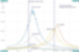
Here is my graph of the 5 coils C-core VIC transformer using all the exact values of the air coils from 100Hz to 10kHz from Dynodon excel sheet.
This is what my impedance analyser measured with only one WFC attached with rain water in it. I did a scan from 10kHz to 30kHz.
I give you measurements of two core materials used in this transformer and you can see what is happening with the frequencies and the impedances. Remember Stan was using a lower perm core without airgap, so his frequency is much higher!!!
Now the main question is why this thing has high impedances on frequencies where the WFC capacitance can never have LC resonance between positive coil and WFC capacitance because my wfc is too high in capacitance?
And the chokes have high impedance on the same frequency.
But the resonance takes place at 14.4kHz and 16.7kHz so the cell has about 64-80pF instead of 1.1nF what I measured?
Also the chokes impedance peaks are unequal in heights, so there is something missing. If you adjust the Rp (primary parallel resistor) you can adjust the peak heights of the impedances, never the frequency!
My thoughts:
This has to do with using only one WFC instead of the series WFC array and or using multiple VICs...
Coil tests very accurate
https://1drv.ms/x/s!AqxyHUVb2_mlkIxaRraALGReXva9TA?e=c8WvCW
IF you down load this Take the Time to forward to universities

Stanley Meyer's VIC - Double Amplitude modulated Resonant Waveform
13 Nov 2022
The "Resonant frequency" is tuned at: 16,7 kHz
The "GATE frequency" is tuned at: 2,98 kHz (create First Amplitude modulation)
The "Unipolar rectifying" is at: 50 Hz (create Secondary Amplitude modulation)
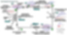
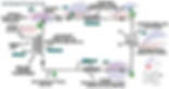
My Circuit diagram:
https://drive.google.com/file/d/1BzrNQs4b4nko5rdOo5qFbVuhpLgxS1kJ/view
The Original Meyer`s Waveform (crop):
https://drive.google.com/file/d/1vwWRN18kFEgkbWSpi39coI32eJdq7I4y/view
The Original Meyer`s Waveform (full):
https://drive.google.com/file/d/1zXrNAHGDlKqFcIbCYWwRp_hB5Cqq3ujI/view
Andrija Puharich`s Waveforms:
https://drive.google.com/file/d/115HZhWPbZDpojLf5E642KtHBBZvZzbOd/view
https://drive.google.com/file/d/1EILxF-YUcHCk7Pw5q1i13xgTH4V61nqK/view
As you know, Stanley Meyer`s VIC have "open core" /broken ferrite core/:
https://drive.google.com/file/d/1ykz3u-AXmEBKW5KPRY6XV57-doJkc6Av/view
In this picture it can be seen, that the broken ferrite core, is not between Primary coil and Choke C2:
https://drive.google.com/file/d/11gXU1NuJnCabAoyMwv1jdVN7is-deIzr/view
The "broken ferrite core", must be between the Secondary coil and Choke C1.
This is also indicated by the blue color of the core tape - it is near to the "blue coil" - the Secondary coil.
If "closed ferrite core" is used, the waveform is extremely "unsymmetrical":
https://drive.google.com/file/d/1LJPC-crWwguP0NpQa_PzjbWG7ShwDGUY/view
By changing the number of windings of C1 and C2, it is fine-tuned the Resonant signal`s DC Offset, but "coarse" balancing is done, with an "open ferrite core"!
VIC Coils direction:
https://drive.google.com/file/d/1815MGpor7KOemrd9Kwem-go09n1n7GFF/view
.jpg)


.jpg)


1 vic for 2 cells &
WFC cells in Parallel
-
10 Vic Direct to each 10 cell
-
Relay scaled vics 10 Vic Parallel
-
to ten cell in series or in pairs

Relay Triggered VIC'S 10 Vic Parallel
There are other simple version 9xb 9xa which work fine for care and much better than using salts. as show in VOLTROLYSIS ASSEMBLY VERSION MAP . HERE
SO WHY PURSUE THIS COMPLICATED ONE ?
This version 6 + of Flat core vic was to be the best maximum efficiency for making BULK
nano bubble water fuel and or GTNT gas for example prior to filling a car or on demand water fuel filling.
These water fuel format can go direct into a injector
If nano bubbles are in the water you can fill up with water with nano bubbles init which can last up to 2 years and or be made on demand back into the water .
So yes we are going to and have gone to great lengths to master this and teach it .

Relay scaled vics 10 Vic Parallel
When two power sources are connected in parallel, the circuit voltage will double.
The current through any branch of a parallel circuit will be less than the total circuit current.
So perhaps the first C-core transformer positive choke output connected to the second C-core transformer negative choke output balances the impedances.
If we use multiple WFC in series (Exciter Array), we think Meyer had ten cells series connected, he needed ten C-core transformers to get the voltage needed to do the EPP. (1000V to 1500V per cell). My idea is that he had ten transformers running at the same frequency but all had their own driver circuit connected in series. (C-core VIC voltages adds in series)


REMEMBER join as a Subscriber HERE and join our Patreon Here to help advance this knowledge Page , this circuit is being saving at this moment due to importance i post as i do each day

The Equipment
I searched for a cheap solution measuring impedances for a long time and found an Evaluation Kit with this tiny chip:AD5933: 1 MSPS, 12 Bit Impedance Converter Network Analyzer :)Here is the link with all the information: link
Impedance Measurement
My thoughts:
I tried to match the chokes impedance, but I think it's "impossible" to match them with only one C-core VIC transformer. Still not sure yet!
But looking at the graph we see the choke impedance on the same scale, but as you can see they have not equal resistance at the same frequency.
If we put Meyers theory to a test and want to match the impedance to restrict our current to the WFC then we need to balance the impedance with adding equal amount to both chokes?
for a cheap solution measuring impedance for a long time and found an Evaluation Kit with this tiny chip:
AD5933: 1 MSPS, 12 Bit Impedance Converter Network Analyzer
this is what you have: EVAL-AD5933EBZ
Looks like a DIP meter for low frequency measurements.
Search on ebay "Impedance Analyzer" and you know it! or EVAL-AD5933EBZ
Impedance Analyzer link
That's the one, it looks difficult to use at first, but if you master the setup then it can be helpful.
http://www.analog.com/en/circuits-from-the-lab/CN0217/vc.html
looks like we can get one here: http://www.digikey.com/product-search/en?wt.z_cid=ref_hearst_0211_buynow&site=us&mpart=EVAL-AD5933EBZ&v=1127&v=505
Here is the link with all the information:
-
Order Link
-
Spec Sheet
Software
www.infolytica.com
www.integratedsoft.com

How to input to simulation software using
a highly variable water cap?
By using a known cap as a substitute for the cell, the secondary inductance could be estimated by monitoring the current on the primary by pulsing a fairly low voltage there in order not to brake the cap.
The frequency at hand would be found at the minimum primary current and the secondary inductance could then be derived by the formula F = 1 / SQRT (L x C).
After that then the cell capacitance could also be estimated using the same modus operandi by pulsing low primary voltage and check for the lowest primary current.
Same formula would then give the C part of it all.


I agree that the chokes need to be matched to get equal but opposite polarity.
As for the equipment of Stan's, when I had it here, my observations of how it was hooked up, was as follows.
-
There were ten vic cards and coils.
-
There were ten outputs to the ten tube sets
-
The VIC control panel had ten outputs meant to go to the cell.
-
All the signals from the ten VIC circuits went out ten different pins to the cell.
-
So that tells me he originally made it to be one VIC to one tube set.
If all the VIC circuits were meant to be tied together,
it would have made sense to do it inside the control panel and not outside going into the cell.
When I first saw the cell wired in series, that through me for a loop.
My thoughts were that something had changed and he or someone else rewired it.
As anyone knows, in series, the tubes share to voltage between them,
so yes, like you said we need 1kv-1.5kv per tube total.
So for ten tubes in series, we would need 10kv-15kv input to the cell.
One thought that I have on this subject is, seeing how all the tubes are in the same bath of water,
maybe the voltage applied to the tubes all add to the water to give us a total equaling the applied voltage. Say we send 1kv to a ten tube cell, we would have 100 volts across each tube, but maybe the ten tubes will all add together to see 1kv across the water, since their all in the same water bath.
That's something I ponder.
I checked out the link, but it's not something I will be looking at, at this time.
Don
UPDATE: I did some more impedance measurements on the VIC transformer.
More thoughts:
Looking at it makes me wonder if the total impedance with a type of water as load, has to shift to the maximum impedance of the VIC transformer resonant frequency where the chokes have maximum impedance or the other direction.
Meaning the VIC is too low in resonance frequency for one WFC as load.
Where the maximum impedance is on 17.8Khz, but the chokes are on 15.7kHz, somehow this needs to shift...?
Maybe lowering the inductances of the VIC coils to get higher frequency or change the WFC capacitance (not an option, I have only one cell)!
The single cell with
-
Tap water was LCR measured at 10kHz and has 3.3nF 18ohms.
-
Distilled water LCR measured at 10kHz and has 1.28nF 105ohms.
The true capacitance is lower on 17.8kHz where the impedance is maximum in the graph!
So there is a impedance difference using different types of water in the WFC.
If I short the VIC chokes (always dead short condition, even with cell attached) we compare both frequencies of the chokes impedances and the total impedance, needs to be on the same frequency. This total impedance is changed by the resistance and the capacitance of the WFC.
Both impedances of the chokes also needs to be the same to get the equal but opposite polarity voltage amplitudes.
Webmug, what you are finding out here, may be the reason why Ronnie Walker says we need to build the chokes to match the cell. He also claims that it can't be done with only one tube set
Instead of quoting impedance, if you start explaining as resistance, inductive reactance, capacitive reactance separately, and then quote the impedance, you should be on top of this.
it is a dielectric setup, use the impedance differences between coils for step charging, impedance matching for resonance network and capacitance for dielectric discharge.
NOTE for chart Above
for understanding the methods and thinking path
One thing I notice is how high the impedance values are at resonance. Their in the millions, is that right?
One of the first graphs you measured the cell with tap water and distilled. They appear to be @ 1khz apart. This to me would be a problem for tuning if we don't stay with the exact same water when refilling the cell. So if it is important that we tune into impedance matching, this is a problem.
So saying that, do we need to match impedance values in ohms, or just the frequency that gives us the maximum impedance. I think trying to get the same impedance numbers for all components would be impossible. Getting all components impedance at the same frequency is possible, if we don't use different forms of water.
The impedance is matched to the cells and the resistance (Re) also depends on the type of water and water number of gaps and gap sizes. Resistance (Re) is also affected by the temperature of the water.
VALID CORECT COIL TEST
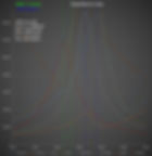
This is the impedance map of my VIC transformer with Dynodon's coil measurements from the excel file.
I tried to get the air-inductances the same as measured in the sheet.
Frequency sweep was from 10k to 30kHz.
Note:
My cores are not the same what Stan had, so the frequencies are off. Right now my coils on a core have higher inductances, but all the coil relations are the same. Core material types are in the attachments. I tested two cores.
VIC was connected at one WFC with rainwater in it.
Update:
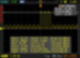
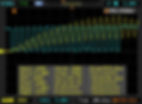
Scope graph, no WFC attached!
yellow trace CH1 is between secondary and negative choke and positive choke output,
blue trace CH2 is between secondary and negative choke and negative choke output,
purple CH1+CH2.
Differences in type of cores.
Download
Russ
Coil Tests
This File is large may not open in browser or ap this is a normal thingp with out download
any issue email Dan
https://1drv.ms/x/s!AqxyHUVb2_mlj_tsTuagDrq4KBg-8A?e=WsDc2T
Webmug
Coil tests very accurate
https://1drv.ms/x/s!AqxyHUVb2_mlkIxaRraALGReXva9TA?e=c8WvCW
IF you down load this Take the Time to forward to universities
Ronnie Walker says we need to build the chokes to match the cell.
He also claims that it can't be done with only one tube set.
Here it is. There are 512 data points from the impedance analyser scanned from 10kHz to 30kHz.
Webmug
Coil tests very accurate


Yes, the inductances of the secondary and the negative choke are in series,
but are magnetic opposing (C core back to back), we want current restriction.
So if both voltage amplitudes are equal but opposite from each other there is maximum current restriction! Yes?
{Lt = (L secondary + L choke negative - 2M) = L choke positive} You need to know the core material, because this changes the Mutual inductance between the coils.
That's why I build a couple of coils first with more and less turns and found a good match with the inductances.
And guess what, all the coils resonate on one frequency simultaneous. That's why a feedback coil can work and pickup the voltage phase from the swinging magnetic field in the core through all the coils and compare it with the primary gated/pulses.
I grabbed a couple of scope shots today and want to make a new diagram how the signals look with the new approach.
When looking at my signals I noticed my secondary frequency is a little off resonance so it has not the maximum voltage amplitude so I need to tune I a little more... It's pretty difficult to get the coils to match.
Now the most difficult part is when we want to connect the WFC... The resonance frequency is found from choke positive inductance and wfc capacitance (plate). We can't tune on one frequency if the plates are different, my understanding, then it has a different charge (voltage) at the plates. And the resistance, not sure yet.
============================
MUTUAL inductance calculation
a) { L choke positive = (L secondary + L choke negative - 2*M) } opposing configuration
and think about this:
The calculation of the total inductance Lt,cc [choke coils] from the TB:
b) { Lt,cc = (L choke positive+ L choke negative + 2*M) } aiding configuration
M=k*sqrt(L choke positive* L choke negative)
This means that the inductance of both Chokes in series with the WFC in between, has the aiding configuration and has higher inductance than the secondary.
-
The secondary frequency divided by 2,
-
The diode (half wave rectifier),
-
But the chokes frequency is a frequency doubler.
-
The secondary has opposing configuration and lower inductance.
Example:
secondary frequency 16kHz --> 8kHz chokes
the negative choke creates a double frequency (phase shifted 180 degrees) of the positive choke.
The frequency is calculated from the WFC capacitance and the Lt,cc inductance(b)
so you can calculate the secondary inductance (a) (frequency times 2).
Primary, feedback, secondary, positive choke and negative choke are all in synchronization.
i post two screenshots of the input output signals at the VIC transformer. Here i wanted to generate the resonance frequency signal on the VIC core (all in sync with the coils). This signal is continuous with a minimum voltage offset then picked up from the feedback coil. It is the main target frequency that the VIC transformer is resonating on.
In the gated offset voltage (higher voltage pulses) we see the stepping (charging of the choke) with higher output voltage. This would charge the WFC series array with little current (because all is on resonance).
The blue scope trace is the output signal from the VIC transformer. The signal may never go under arbitrary “lowest voltage potential ground” voltage level and is always unipolar pulsed.
The scope shots are 3 years old and improvements are needed/made on the used pulsing circuit. This stuff will eventually be digital controlled.
Have a great day and keep building and testing Meyer tech!

Air in the Gap
I was reading Patent 4,394,230 today and he shows the spike that was in video figure 6A in stage discussion.
It occurred when open circuit condition was created by removing water from between plates. In the stages he talks about the conditioning step that Stanley also references.where water conditioning step.
Interesting he states there are very little bubbles even though gas is being generated and that process stops (Stanley was interested in the ionized gas!) He also states that increasing power did not cause gas generation to restart.
Reversing plate voltage did and also vibration did but that caused voltage spikes.
I also wondered if relaxing time (t3) would allow cycle to be restarted? It this works it might explain the 11 cells in the car so always one or more cells are outputting gas while other are recycling. Note: In patent he states not all stages he lists are required.
Some of Stanley's Patent and his Birth of New Technology, Puharich's Patent 4,394,230 and both of Ronnie long threads and several of the other threads.
Having done that in a very short period of time I see a lot of similarities between Puharich's Patent and what Stanley is doing.
To me it appears Puharich discovery process in his medical work and patented it.
He even states this in one of his documents. He approached it from a science point of view and had tools most experimenters do not microscopes, spectrums analyzers, and access people to looks at the physic of process.
In his 7 phases he describes what is going on in each phase and it appears he has no problem repeating things and even points out where process hangs up.
As this is not much use in medical field I think we just moved on to other things as states only 70 to 80 percent effective. I guessing this is where Stanley started is experiments because he had a problem he wanted to solve.
One of things I got out watch his video's and his documents Stanley is more of engineer (so am I) we take a different view we state a problem then try to figure out solve it.
Puharich in patent provide several key things.
1) Process to split H2O into gas by his method works
2) show steps to do that (AM and FM modulations in certain frequencies ranges)
3) Event talks how to combine and frequency ranges to use
4) showed a cell design that works (reminds of Stan's injector)
5) documented problems with his system working i.e. gas cells stick to walls
6) process as described is only 70-80 % efficient
I guessing Stanley looked at this process as he was looking for another source of energy.
It, is 70-80 percent efficient can I make it better
Having read the about documents and trying to figure what I needed to do to get involved I decides I need to know a couple of things.
1) How to solve the impedance of the VIC system
(not my favor things even when I studied this in college)
even started my own spread sheet in excel to help solve equations
(stop when I realized I needed to know more).
20 More about coils etc. (good coverage in threads (lot of good people)
3) The timing of they "system" I wanted to know how AM and FM signal were put together and phased and how the voltage steps where created but also WHEN the voltage steps were applied as both Puharich and Stanley state their is a conditioning step that "must" be satisfied before moving to next steps.
In the two threads WATER FUEL CELL Technical Brief and Understanding How Stan Meyers Fuel Cell Works, Ronnie and others have provided a wealth of information.
The work that Ronnie has done just amazes me he duplicated in lot a whys what Stanley did approach it from a systems approach and answer the question what do I need to do to make it
Zooming in
The key to amp restriction is the waveform as there must be an equal amount of negative and positive voltage which one can see on the oscilloscope.
This is where I find most people don't know how to actually use their oscilloscopes or even interpret the readings their oscilloscopes are showing them.
This is the part of physics most people either don't know or failed to pay attention to while in college level physics classes. Here is a video that goes over how to find out the total work done: [size=78%]https://www.youtube.com/watch?v=9q3Cw6dzSZ0[/size]
In this simple video he goes over what to do with negative areas under the curve.
This applies to what is being shown on the oscilloscope as positive reading indicate current flowing through the system. Negative reading means it took energy from the system so if with one pulse the positive and negative pulses are equal the total energy flowing through the system is zero for that pulse.
Then Meyer set up a series of pulses each will put both negative and positive pulses to the water fuel capacitor and again if those energy are equal in their voltages the net energy that flows through the water bath is zero.
I got it really close to zero as the voltage of the positive pulses was around 5 volts more than the negative voltages. So the total work, or in our case current flow, is dependent on the how well one can get the negative and positive voltages to be equal.
The area under the curve shown on the oscilloscopes shows the current that is flowing through the system be it negative or positive readings and one must know how to interpret these readings.
This is why when people say that my waveforms are incorrect I know they simply just don't understand how to make sense of this technology as they just don't have enough education under their belts to be trying to solve this technology.
For they don't understand for every one pulse sent to the VIC transformer you get two pulses in return one being negative and the other being positive in that order as that is how Meyer set up the transformer in the voltage intensifier circuit.
Since the current is being canceled out with a balanced waveform the only thing left to do work is voltage.
Those people showing you their wave forms with nothing but positive areas above the zero line are pushing current through the water bath as that is physics and if you can get them to take temperature readings over time you will find out that the water bath heats up depending on how much current they are flowing through the water bath.
However they know this and will more than likely refuse to take temperature readings over time as that doesn't square up with what witnesses to Meyer's technology say about setup as it ran for over an hour while they observed it.
These eye witnesses tell the water temperature did not change like it should have done if it was standard electrolysis taking place and know you all should have an idea why.
A Word of Caution interpreting the scope shots shown here
To make gas bubbles you must have a DC hitting cell if you read over the total pages here you will see that depending on where you connect your scope you will see ac bounce
keep in mind the best place to read cell is ether side of cell.
the follow scope shots where done by Ed, and put here to let you read and connect the dots
they show some of the interpretation but not all the lower part of this page must be read about lmd and other areas to fully grasp the dc balanced sign DC than and only than will you be close enough to hit air gap bubbles water and gas all at the same moment.
READ on and ENJOY YOUR NEW Water FUEL KNOWLEDGE GOD KNOWS THE NUMBER OF MEN AND MAN HOURS PUT IN TO HAVE THIS PAGE HERE FOR YOU SAVE IT SHARE IT TEACH IT


10 What does it mean
If this is the current passed through the cell, then the area is the number
of kulons passed in one or the other direction.
Correct, and in physics it's known as the ability to do work. Thus if you see someone with a waveform that is only positive they are doing pulsed DC electrolysis and might as well do what everyone else does to make Faraday style electrolysis work better
. But in Meyer's work the waveform is to be balanced with both positive and negative voltages being equal so in this way the work done to perform normal electrolysis simply isn't there as the two areas cancel each other out. In my experiments I have gotten the current down to just 0.3 mA which Meyer calls "Amp Leakage."
This is how voltage can now do work as in this way a very high voltage potential difference can be place on the plates of the WFC which is basically mimicking a thunderstorm in nature.
In the first photo is of Max Millers waveform and the second From Ed another builder where we compare
Things to note we both have the circuit hooked up the same way with the only difference being Max has just two cells hooked up in series and Ed has ten cells hooked up in series.
Basically he over loaded the transformer and as a result it was not able to charge the negative voltage and all of that positive energy went through the water bath.
Now in the last two drawings each vertical line represents one pulse sent to the transformer with a total of five pulses sent to the transformer.
When it is hooked up correctly it always puts a negative voltage ahead of the positive voltage and if the two are equal no current flows through the water bath. But there is always a little energy left over at the end that will pass through the water bath as shown in the last drawing.
Can you see just how important that question is now?
A Builder with a Working Cell
1) he stated that Stan's had said smaller cell's were better never said why
2.) In his discussion on independence balancing he showed why ten cell helped as it added more resistance
3) In conditioning discussion he talked about not using all the available power - start creating bubbles to late is bad (said should start around 2 volts and not enter full gas production until near 12 volts) resistance of the cells will be a factor in this
The procedure is actually pretty straightforward: Low voltage, center tune, up the voltage a tiny bit, center tune and so on until you finally have it precisely dialed in. Once dialed in, you can power up to full voltage from a cold start and it should run.


As you can see from Max's and Ed's waveform when the waveform is right ,
it cancels out the current
as I have the reading to prove it and if you pay close attention to Max's video
you can see heat waves being generated as the current is flowing through the water.
It's just as Meyer stated in the New Zealand video that the current is canceled out by magnetic fields.
The oscilloscope allows us to see the action and verify everything mathematically. In physics these are just work summation problems adding up all the energies and for each pulse sent to the VIC transformer two pulses come out be it one negative and the other positive and as long as they are close to equal there will be little to no current flowing through the water bath as the sum of the energies is zero.
VISION TO SEE
Skills of the Art
Now that its taking shape and it is explained how to actually read and interpret things the oscilloscope shows one can clearly see that these wave forms are pushing current(NOT GOOD) through the water bath as after all the oscilloscope is just a tool to aid us in seeing what is actually going on.


That last waveform is actually correct but the transformer was over loaded which is from Max Miller and again you can clearly see he is pushing amps through the water bath as he just max the dial to show it goes to infinity or until parts pop which they did LOL
SPECIAL NOTE be aware if you push up amps you move from cold voltage to arc voltage which can spark use caution as you enter the next section where you make gas and high voltage and fuels/
NOW TO THE THE REAL
HOME RUNS =no current
Working Builder 1
that's the time base the scope is set for not the frequency.
But yes 19.2kv
Stan said up to 20,000 volts, I am as close as I'm going to get with this VIC.
A Sperm Wave, that is a good name for it Matt,
I think I will adopt it. LOL if you don't mind.
Hv probe from positive of the cell back to the neg of the choke
where the secondary ties together with the neg.
the applied voltage which is 14 volts @ .01 to .02 mamps

Here it is the whole 20,000 volts. As Matt put it "The Sperm Wave"
The oscilloscope is trying to measure two frequencies on one channel (pulse and gate) which it cannot do. That frequency of 485Hz is not the pulse or gate frequency, its more like an average.
NOTE
The reason why pulse and gating can´t be displayed there is that pulse and gating are not synchronized. so they are always Floating against each other and the first and last pulse get cut off more or less. that´s not precise.
But I don´t agree, there are several ways to measure that configuration with gating:
1. if you use a digital scope press "freeze" and you always get a precise momentary scope shot
2. if you use a digital scope use alternate Trigger and feed in pulse to one channel and Trigger to the other channel, then display the mix
3. use the trigger output of your pulse generator and you always get stable scope shots.
PGen TEST pulse Generator serves a trigger output for each of it´s four channels.
But it´s a unique feature you won´t find somewhere else
SO IT SHOULD BE INCORPORATED INTO ALL 2020 and beyond as a important feature
for tuning and training
Example
If Stanley used a 1.1mm gap on his cell the outer tube and the inner tube would have about a 6% difference in size.
L1 and L2. are about 6% different in size if you use Dons numbers.
Im thinking the cell might need to be impedance matched to the coils like
GPS said a long time ago.Correct all the way.. My initial belief was that L2 was smaller so that the electric fields would be equal since each electrode has a different area.
Since the wfc is connected in series the cells do not have the same polarity. On one cell the outer electrode will be positive, but on the very next cell the outer electrode will be negative.
IMO the different sized chokes are not used to maintain an equal electric field at each electrode.

RE Image Above
Is the input Freq 485Hz?
I used Dons Specs about 1.2H and my Vic tuned in at about 16-19 Khz.
I got the same from my simulation. In order to get this thing to run at 485Hz I think I would need about 10H on each coil.
looks close to 10khz, (pulse) gate is way different
-
Each division is 500us
-
so if each division was a pulse, they would be 2khz.
-
But there is 5 pulses in one division,
-
This makes it 5 pulses x 2khz =10khz
The other number is measuring some thing else. (Look at the cursors)
I did some cool calculations and that should be true,
The calculation,
2.18ms = 458.72 hz
So we are looking like just over 10khz
10,666.7hz
There are 16pulses in 1500us
If correct ,
just asking my self if it's half that? As it needs to be a full cycle.
If it's half it's 5,333.335hz
Working Builder 2

Special thanks to Russ Gries and Alex G[s Webmug and others in the
Open Source Science community
That core bring up the inductance very fast!!! :D
I was thinking out loud: have you been testing the self-resonance of a coil on the core?
I think it's important to test, how far off the coils are with the total resonance frequency. If they get Mutual inductance on the core we can see what has changed. Subtracting or adding inductances. If this frequency is in phase with all the coils.
My opinion is that Choke1 and Choke2 inductances are divided --> A=1/(1/choke1 + 1/choke2) so then the secondary inductance factor becomes 1=(A/B) = (B/A) and needs to be equal -->B=1/(1/Sec + 1/Choke2) those have almost the same values! Balance the coils.
Just a wild guess... please correct me if I'm wrong and I will modify!!! Just learning...
I'm still thinking through this with you... that's deep...
but it makes since.
i will say i did some tests with moving the inductors to the same core and the secondary and primary to another. i did not see any real change. as if it dose not madder..
https://www.youtube.com/watch?v=UlV6fpwlsSs#ws
don't forget that what Alex was seeing was a fluke in having a another meter in the circuit...
don't forget that what Alex was seeing was a fluke in having a another meter in the circuit..
That is exactly why you can not get 1 3 5 7 9 cells to work, they have to be paired in two's. (2 4 6 8 10) ect. (1 3 5 7 9) will not work.
Now flat cells are completely different they can be made to have the same surface area on each plate. On the round cells, when you reverse you leads when measuring the capacitance the meter should read the same capacitance either way with 2 cell or a even number of cells.
But when you have odd number of cells you will get a different capacitance reading when you reverse your leads on the cell. And if you do have a different reading it's because your cells and cell housing and caps are not machined to close tolerances.
The closer you are to having the same capacitance when reversing your leads, the better off you will be when trying to match up your coils to your cells
I see Gpssonar saying the same thing in several places, matching the coils to the cells.
He also mentions that its better to build the coils around the cell, because building the cell for coils is difficult.
In these statements what is the thing he is seeing or measuring in the cells, which is used in building the coils.
I see in builders thread everyone talking about the coil resonance. but Gpssonar seems to be stressing more on the cell than the coils.
Does any one else see it that way.
of course the cell is the reactor because here the ionization producing the monatomic ions takes place. so all other parts of the circuit are drivers and regulators for that process.
pulse generation, resonance, impedance tuning etc. are all dependent drivers for the effect in the cell we are looking for.no he is saying don't design the cell around your coils. its to difficult.
instead design your coils around your cell...
he is not saying resonance is not a factor. it is a factor. it is the only reason it works at all. Gps Did say this...
(The positive choke will resonate with the cell as long as the reactances of the coil and cell cancel each other out. The negative choke is smaller because it is below the resonate frequency and will limit current.)Stan even stated that yes the cell and L1 are the LC circuit. indicated by a diagram in the tech brief. now this LC is just all dependent on the frequency.i think this is the ezy part...
============
the other cols are where it gets tricky. theses have to " do there job" something im still pondering over but me and alex explain what we think " there job" is in our video / blog Post.
Pulse Generation - short burst of energy into the circuit, nothing special
no but... a sharp on or of dose help a lot!
impedance matching - matching of resistance between i/p and o/p so that max energy transfer happens, may be something but in our case nothing special
this is EXTREMELY important !!!! this allow for maxim power transfer!!!!
impedance tuning - is it making sure that all the coils in the network have the same inductance, why? shooting for a common resonance frequency. What is the point?
i'm thinning you mean something else here... but tuning is needed. not for the same inductance but for a balance of all coils to do there " job"
when we say resonance, is it coil resonance frequency,core magnetic resonance or DC resonance step charging - what is it?
might be all of them...
I guess GPS 2 core setup should give an idea now, coil resonance frequency or magnetic resonance is not important for him. Although they are a beauty and mystery on its own.
Its the step charging that is important, he wants to increase the charge with step charging logic, doesn't want to negate the charge with BEMF or something like that, so the 2 cores aids him to some extend, but thats not a killer thing, because even in 1 core you could get the same voltage increase, ask Ed. We can also ask Russ on how much significant difference it makes when he switch inductors across cores? there shouldn't be much. if what i say is true then here also nothing special
i found switching the coils around to not have to much effect at all. but one way is better than another according to our theory. now 2 cores is less effective IMO but could be easier to tune. on the other hand the single core is best but much harder to tune.
I want to learn and i really don't want to sound arrogant, so please with all kindness read my post with a humble sound :)
humble is good :)
Now if some one can explain the energy/current flow in the VIC using old school's style, where current flows from -ve to +ve
and then prove me that all that i marked as nothing special is wrong and there is something special. I will really appreciate your kindness in setting my thought process straight.
Where does the -ve start and where does the +ve end in the single core circuit and 2 core circuit. To me its just an infinity circuit. there is always a continuous flow of energy, as long as the nature induces something in the circuit to do so. Alex Petty could answer that, with his recent experiment.
Lots of misinformation, hope and wish you guys nail this.
you did see this post yes? http://alexpetty.com/2014/10/14/operating-meyers-vic/ i have never seen anyone else explain it quite like this...
webmug, interesting thoughts.. i did some calculations but did not get the same out put. can you do the math and show mw that there the same? i was off ( 73.81mH to 96.44mH)
OK so close but not all there... mabet i need to adjust it till it dose match.
but there are still some problems. there needs to be more calculations done on this on to p of those... still looking at what.
~Russ
After re-thinking about those calculations my conclusion is that they are wrong! If even number of cells are connected the chokes has to be wound with the same wire length. So the factor is always 1. Why the measurements from dynodon excell sheet have not the 1 factor are a question. looking at one WFC the surfaces have unequal charges so maybe this is why the choke coils had different wire length.
But I still don't know for sure if one WFC can work with one VIC transformer? I think it won't work, because it has too low voltage potential!
Testing Resistance Note
its just like battery's in series. you still have both poles,
one way to look at it is that there now a single "capacitor" so they do have polarity.
if we are looking at this system as tuned circuit then this is going to be extremely important to match everything.
resonance happens when XL and XC are equal. so we must match the secondary to the cells
. ( secondary is XL and cells are XC)
so this means that the chokes are "voltage amplifier's." as well as amp restricting devices
i would think that the chokes would need to be impedance matched to get maxim power transfer and boost voltage/current with in the tuned circuit?
am is way off here? dose this not make scene?
OK here is what i measure when distilled water is filling my cells and there are 6 connected in series,
measuring +on the inner tube and - on the outer tube: 241.6pf
that's with my cheep meter, that's suppose to be more accurate... so that's what im using.
my question is how do we go about impedance matching the cells to the inductors?
whats the calculation?
i would say we use 7500HZ for our frequency and calculate from there?
another question is do we need to calculate the L1 and L2 in to the secondary inductance to do the math correctly? so:
(secondary , L1 , L2) = total xL and all 6 cells = xC ??? we need xL=xC @ 7500hz
=====================================
Primary 10.5 ohm
Load resistor 220 ohm
you get 10.02 ohms.
Then multiply that by 7, the ratio of the transformer, you get 70.14 ohm
This is the exact resistance of the secondary coil on Don's spec sheet.
So my guess is to add all of the secondary side S1+L1+L2 = 70.1+72.4+76.7 = 219.2
219.2 ohms sure looks close to 220 ohm..
If the cell was 10.5 ohm at 20,000V you might have a balanced impedance match for your high voltage standing wave generator. (VIC)
==============================================================
so my question would be are we trying to impedance match the primary to the rest of the VIC or are we trying to impedance match the secondary to the capacitor ( cells)
For RF we consider impedances. The condition for imped
ance matching
is that real part of the impedance should be equal to
the real part of the
load and reactance's should be equal and opposite in char
acter. For
example if our source impedance is R + jX to achieve matchin
g our load
should be R – jX.
If we assume that we have a chamber with capacitive dischar
ge the
impedance in general will be R – jX. Generator typical
output impedance
is 50 Ohms. Then the matching network has to make 50 = Rl
and jX = 0."
The positive choke will resonate with the cell as long as the reactances of the coil and cell cancel each other out. The negitive choke is smaller because it is below the resonate frequency and will limit current.Take Webmug's advice look into how you can get all the coils to resonate at the same frequency.
Separate note
Stan says in the NZ video that the resonance changes as more bubbles in the cell effect the dielectric property but I don't think it will drop close to air because there is still a dielectric path around the bubbles,
I would say it might drop to between 50 and 60 but not down to 2 or 3. If you use a capacitance calculator, a reactance calculator etc then the calculations come out at impossible ranges but I guess we are dealing with unknowns so anything can happen.
Well Nav, I agree that the capacitance wasn't also changing much. If the capacitance would drop down with 2 or 3 dielectric the choke LC is out of range. Stan had his 5 coiler VIC designed for natural rain water. So the ppm didn't change too much (TB water table). All that changed could be tuned with the range of the scanner electronics.

My conclusion is that the above impedance match is wrong!! Prove me wrong...
~webmug
Everything I have said here has been said in my own personal thread. Good example is what has been discussed here about the dielectric changing from water to gas.
How many times can you go to my thread and other places and show me where i told everyone that you had to start at 2 volts and tune and raise the voltage to 4 volts and tune and so on and so on.
What is this telling you? I will answer it for you, it is telling everyone that i was tuning into the dielectric (properties of water) even Stan told everyone that was what he was doing. I would assume people has no clue what the dielectric properties of water is.
I can't help if people don't have the common since to research about things they know nothing about.
Still wondering how Stan came up with the constant Re=78.54 ohms value. It is correct, he mentioned that value all over the place. Looking at his patent there is an analysis how he did the amp leakage test comparing different configurations to restrict current. In the graph we see different level of voltages and configurations. Also in the table with different types of water we see the Re of 78,54ohm.
So every water capacitor has an Re of 78.54 ohm... ?
Using the minimum gap separation of 1/16 inch we get maximum gas generation with maximum voltage.
I ask this because he said it's the gap separation which determine the operation but does this mean it's always 78.54 ohm no matter the gap separation?
Is this always valid using all kinds of water? The table with water-types states different ppm...
(rainwater 16.1ppm TDS ->25.2microS/cm).
@Ronnie,
I hope Ronnie would answer my question, why you changed the gap spacing in the WFC?
Also using the Impedance Matching Formula, I get a low turn count using the (secondary, chokes and Re) resistance.
Did he used the 1:30 ratio for the secondary only or what?
===============================
Something for you all to think about. On the note of the inductors being different values. One very interesting thing that you should recall in almost all the drawings is that you See a variable inductor on the negative side. Why is it that Stan has a variable inductor in the drawings? Have you ever seen one of his devices with a variable inductor? The answer is no.
The reason for this in my opinion is that if you know how to engineer it to the correct specifications you do not need a variable inductor. I truly think that he did this to show us people who are trying to replicate it that you need to tune that particular inductor. So basically it's a very simple diagram saying "hey dummy try this and see what happens"
Anyway, just some food for thought.
Keep up the good discussion. We will get there. It's all going to take time. God bless ~Russ
Hi,
If you read the tech brief p3-10 Memo WFC 422 DA about variable inductor coil, he makes it clear why it is tunable. Movable wiper arm fine tunes "resonant action" during pulsing operations. The relationship between them, electrically balances the opposite electrical potential across voltage zone.
Yes, it is not physical tunable with a dial, it has a tuned fixed relationship.
I would like your opinion about some core material.
Typical Properties:
Mn-Zn Ferrite
Initial Permeability 1200 Most using 2000 Perm
Maximum Permeability 7500
Saturation Flux Density 5250 Gauss
Remanent Flux Density 2100 Gauss
http://www.cmi-ferrite.com/Products/Materials/data/MN67.pdf
EDIT: http://www.cmi-ferrite.com/Materials/Datasheets/MnZn/MN67%20ISO%20WEB%20DATA.pdf
Custom core can by made with the exact dimensions provided in Dynodon sketches.
The parts will be machined from an iso-pressed block of ferrite.
Minimum order would be 10 pcs.
We need 2 pcs for one VIC unit.
National Magnetic s Group
Tuning scope

Now I believe that my chokes are not tuned yet. I need to tune one to the other on the same core. So I'll try again Videos Part 4 is where it's all happen. 1-3 are set up and such..
Notes
if you are using a grounded scope your probe ground connector will connect the secondary cell circuit to grid ground. I assume the same will happen by using an usb scope because the computer is grounded.
the plastic bag under the pulse generator pcb is conducting to avoid static discharge. It´s a good idea not to use it under the pcb or any electrical circuitry.
Just watched all of your you tube videos on building your VIC, The coils were afecting the sound so some things I could not hear.
Did you say your cell was 260 PF ?yes 252PF that's with 6 in series
Note:To callabrate or test you meters just test a known cap or inductor and wichever meter works best use for all testing.
I did some reading (thanks GPS) and I found out that I had L1 and L2 reversed on my VIC.
The Larger Coil Connects To The Pos Side Of The Cell or D1
High Voltage Probe
6.5 KV probe
but now he´s using a 15 KV DIFFERENTIAL PROBE
probe for actual cell voltage measurements.
potential free measurement. better look for a high voltage potential probe like Ed Mitchell uses. it´s in the $ hundreds but it works up to 15 KV potential free.
these differential probes are black boxes built for high voltage measurements with integrated HID safety means and they all have a power supply of their own.
their generic function is a resistor array of course but an operation amplifier with differential inputs generates the signal output from differential input. both inputs are floating at a high resistance potential related to scope and/or system ground.
the 6.5 KV probe worked fine up to 9 KV over the cell but we can´t be sure that that works too long and so in the meantime he had to use the 15 KV probe ... and for higher voltages we need it anyway now ...
Another option is DP 30
30kV (peak to peak) 50Mhz differential probe from Pintek at 400€ on this site :
https://www.globalmediapro.com/dp/A2JGB4/Pintek-DP-30K-Differential-Probe-30KV-50MHz/
you'll have to include taxes + customs fares (~140€ for Belgium) to pay at your local post office before receiveing your package ... so that's ~550€ for this probe


I purchased a MIcsig DP2003 High Voltage Differential Probe (Approx. $240). It has 2 ranges 560V(200x) and 5600V(200x) as I want to be able to check cells with higher. The have another model the Micsig DP1003 with 50x/500x up to 1300V would have been a better match to my O-scope as it has a 50x range. The one I purchased works great, but the voltage displayed is low by a factor of 2. When I was looking for probe, I saw reviews that said O-scope would just to range of probes or you could download new ranges, however, that did not work for my older scope. I will try to make note of this when I post scope pictures, so people know value for it on screen is incorrect.
As the differential probed does not use the system ground it give a true reading on the voltage across the interface to the cell and very clean signal as all the common mode noise is removed. In screen shots I set the probes to show the pulses up to match the signal going into primary coil which I am using as frequency reference, you can do this by either moving the probes or using invert function of scope. This is for display purpose only as the only signal the cell sees it the one on cell interface.

That's it but there are 2 more sets of probes one with hidden clamps in tip and one with pointed tips for probing. I am using the one with clamps in tip for my testing. One of the YouTube reviewers had both and said this DPS2003 has better quality probes but that they have basic the same electronic inside. You can see the additional probes in photo.
By the way $240 include shipping from eBay Amazon was out of stock and did not know when they were getting more.

Building Probe in a Remote place no money ??
anyone find an active probe that can handle Meyer voltages that is less than $3k ... ?
The answer is yes, a fluorescent bulb will do the trick with no problems, It will tell you all there is to know if your getting high voltage in the cell or not, it will tell how much voltage your getting into the cell by how bright or dim it is..
It is the Best Cheap Probe on the market and it want ground out the cell either.. You can even stick it in the water bath or outside your cell..still want short it out..
If i remember right it is good down to about 700 or 800 volts and above. It really glows bright at 20KV.

Do we have ideas how to accurate measure low AC current/high voltage
(range 1 - 30mA, 1-50kHz) with a sense resistor (low,high side?) or a sense coil?
I can't find a decent active differential instrumentation amplifier below
100kHz with scope connector signal output.
Meyer states if we adjust our B+,B- voltages we restrict current.
But I think the coils won't have exact current 90 deg out of phase
(LEICIE) if we also have voltage 180 deg out of phase...hmmm Leakage!!
Perhaps both currents wont be equal at all?
We need some low cost DIY toy
(differential current sense instrumentation amplifier)
to measure the B+,B- currents...2 or 3 channels...
https://www.tindie.com/products/LDLabdevice/accurate-high-bandwidth-currente-probe-100ma/ $$$
breakout-pcb?
devkits?
http://www.analog.com/media/en/technical-documentation/data-sheets/AD8418.pdf
https://wiki.analog.com/resources/eval/ad8418-evalz
here back up link
Accurate High Bandwidth Current Probe (100mA)

Very accurate (uA) high bandwidth AC/DC current probe (100mA / 10mA range)
Designed by Labdevice in Switzerland
https://www.tindie.com/products/LDLabdevice/accurate-high-bandwidth-currente-probe-100ma/
Very accurate (uA) high bandwidth AC/DC current probe (100mA / 10mA range)
The active differential probe is a high performance, low cost current probe which can be used together with an oscilloscope for precise AC/DC low current profile measurements from the low uA range up to 100mA.
The USB powered current probe is an ideal tool for electronic development where accurate measurements are needed.
It has a switch for two different ranges. This makes it ideal for accurate measurements in a specific range. It also has a switch for bandwidth limitation. This feature can be used for measuring currents in the audio bandwidth or low noise measurements.
The shunt resistor is negligible small. The large output dynamic range makes it possible to read very small current from any standard oscilloscope.
For more information and details regarding the specification please have a look into the datasheet.
The delivery includes: - Labdevice current Probe - Measurements cables - USB cable
Where to Probe VIC
the voltages are measured between points D and E (webmug notation).
may i suggest to always note and publish those D-E voltages produced because they are the real stuff looking at the WFC dynamics. of course all other measurement points are also POIs for overall operations dynamics but D-E is where the rubber meets the road ..

May I suggest to design an own resonant frequency simulation so that experiments and forecasts can optimise in steps of iterations.
I re-linked. Tell me if you can see it OK now.
Here too is a version that has a nice time scale with a well balanced charge flow speed:

ps Did say this...
(The positive choke will resonate with the cell as long as the reactances of the coil and cell cancel each other out. The negitive choke is smaller because it is below the resonate frequency and will limit current.)
Looks like the Pos choke must be just the right size to match the cell or were DOA.
If we knew the exact size of L1 we might have a chance at the other 2 coils.
We could try to use the known numbers from the cell and match them to L1?
Note: Just got my SS tubes in and will be making a new cell this week....and thanks Russ for the bobins there great.
so Stan even stated that yes the cell and L1 are the LC circuit. indicated by a diagram in the tech brief. now this LC is just all dependent on the frequency.
i think this is the ezy part...
the other cols are where it gets tricky. theses have to " do there job" something im still pondering over but me and alex explain what we think " there job" is in our video / blog Post.
more testing / information is needed. one day at a time!
================
webmug, interesting thoughts.. i did some calculations but did not get the same out put. can you do the math and show mw that there the same? i was off ( 73.81mH to 96.44mH)
OK so close but not all there... mabet i need to adjust it till it dose match.
but there are still some problems. there needs to be more calculations done on this on to p of those... still looking at what.
~Russ
After re-thinking about those calculations my conclusion is that they are wrong!
If even number of cells are connected the chokes has to be wound with the same wire length.
So the factor is always
1. Why the measurements from dynodon excell sheet have not the 1 factor are a question.
looking at one WFC the surfaces have unequal charges so maybe this is why the choke coils had different wire length.
But I still don't know for sure if one WFC can work with one VIC transformer? I think it won't work, because it has too low voltage potential!
the design is 10 cells and than 10 vic in parallel than it works
~webmug
I think the VIC and WFC are very sensitive devices...
For example the WFCs connected in series..(2,4,6,8,10 etc) .
If two exciters are connected in series and the plates are not exactly equal in areas (+-+-) what will happen if you connect equal chokes at both sides?
Same question but different chokes and different plate areas?
So if you connect 10 WFCs in series, then what happens if they do not have equal plate areas? This creates leakage!!!
If we want current restriction all of the areas must be equal and chokes must be equal, or not?
Even the wire lengths are a part of the circuit?
How do we see this with the Injector Design?
Are the areas (anode, cathode) equal in charge?
If the chokes are wound bifilar they must be equal in charge and areas, right?
with the choke 's being even...
more questions than answers...
but the injector is not the same too. the injector is not really submerged like the WFC resonant cavity? could play a roll?
Maybe the Injectors fired in even pairs or at the same time?
So charge area's where the same?
I did some new VIC tests (trial and error), I cut my 3D printed bobbins to create separate coils and tried coils with different windings on them. I hope this can be useful!!!!
I did find a possible solution trying to match the equal but opposite voltages...no WFC array connected yet!
First I want to solve the Mutual Induction part with all the VIC coils on a core.
I use a LCR meter set on 1kHz test signal;
Connect the Secondary Finish end wire to the LCR probe;
Connect the Secondary Start wire to the Start wire of the Choke2 (negative);
Connect the Finnish end wire choke2- to the other LCR probe.
Measure the L inductance, write this down.
Disconnect the LCR probes;
Connect LCR probes to Choke1+ Start and Finnish wires.
Measure the L inductance, write this down.
Explanation:
Choke2 is opposing the secondary coil, so the Mutual inductance is subtracted from the series connected secondary and choke2 circuit. Lt = L1 + L2 - (2M)
To get he same but opposite voltages from the VIC, the outputs of choke1+ has to be choke2- equal but opposite voltage potentials...
So inductance of the choke1 has to be the same value as the series (secondary + choke2 - 2M) inductances!!!
But there is a catch, when we use a different test frequency (100Hz to 10kHz) those inductance values will change on my LCR meter for reference values so I use one 1kHz only. (there is one freq where inductances are matched, this is also the LC choke1,WFC resonance frequency)
(using a differential HV probe)
I noticed that the secondary coil has the same frequency as the choke1 and choke2!!! If the VIC circuit is all connected, except the WFC and I measure over the secondary coil we see a nice (linear) rising AC voltage. If I measure over the Choke1 it has the same (linear) rising AC voltage but higher amplitude. Choke2 generates the same voltage equal but opposite. Measuring over choke1+ and choke2- generates DC unipolar pulses never go under ground level. I see rising voltage amplitude.
Work in progress, more work is needed connecting the WFC changes the characteristics of the coils. So the LC of choke1 with the WFC is the matching frequency Xl=Xc where the series (secondary and choke2 -2M) has to be resonant with.
~webmug
Webmug, It took me a few rereads before I was able to get at what you were describing. Your saying that because the secondary and the negative choke are in series, their inductance adds together. With that inductance value it should match the inductance of the positive choke, right?
I can see where your going with this. Before we thought that the difference between the size of Stan's choke were to adjust for the difference in the surface area of the tubes. This is another idea that needs some looking into. I will take a look at my readings I made of Stan's coils and compare them to this idea of yours.
======================================
======================================
Yes, the inductances of the secondary and the negative choke are in series,
but are magnetic opposing (C core back to back), we want current restriction.
So if both voltage amplitudes are equal but opposite from each other there is maximum current restriction! Yes? {Lt = (L secondary + L choke negative - 2M) = L choke positive}
You need to know the core material, because this changes the Mutual inductance between the coils. That's why I build a couple of coils first with more and less turns and found a good match with the inductances.
And guess what, all the coils resonate on one frequency simultaneous. That's why a feedback coil can work and pickup the voltage phase from the swinging magnetic field in the core through all the coils and compare it with the primary gated/pulses.
I grabbed a couple of scope shots today and want to make a new diagram how the signals look with the new approach.
When looking at my signals I noticed my secondary frequency is a little off resonance so it has not the maximum voltage amplitude so I need to tune I a little more... It's pretty difficult to get the coils to match.
Now the most difficult part is when we want to connect the WFC... The resonance frequency is found from choke positive inductance and wfc capacitance (plate). We can't tune on one frequency if the plates are different, my understanding, then it has a different charge (voltage) at the plates. And the resistance, not sure yet.
Regards,
~webmug

Webmug, I guess I'm lost when it come to the value of 2M. Where is this value coming from? Can you give me the math of your test. I mean what are the values of the secondary, chokes and 2M so I can see the Lt as an answer.
Also the value of L1 to see the match when done with the calculations.
================
I used my LCR meter set at 1kHz test frequency and measure the (secondary and negative choke) inductance in series connected.
This value is the total Lt inductance. So measuring the two coils separate( L sec) and (L negative choke) it follows the Lt = L sec + L negative choke +/- 2M. The + or - 2M depends on how the coils are connected and configured on a core.
I use a C-core, following Meyers circuit they are oppose each other (negative) correct me if I'm wrong.
Mutual-Inductance
For example I measure 5H over both coils, they are in aiding configuration. And Lsec=1.568H, LnegChoke=1.726H.
Using formula mutual inductance: 5=1.568+1.726 + (aiding) 2M -> M=0.881H.
We want oppose configuration - 2*0.881 gives 1.533H
And the positive choke must have 1.533H to generate equal but opposite voltage amplitude.
M (mutual inductance) depends on core specs and distances of placing the coils on the core. Different coil inductance, changes the M between other coils. So I found it by testing and making different coils more or less windings etc.
I don't know if my diagram is helpful but you can see the voltage waveforms (c,d) and (a,e) and have equal but opposite voltages... I also added an overlay waveform, so you can see the equal but opposite voltages from both chokes.
Corrections and comments are welcome!
Update: attachment with the voltage amplitude across the chokes.
~webmug


found a site with the formula you posted and did the math for your setup.
Lt=5H, Lsec=1.568H, Lnegchoke=1.726H
Lt= Lsec + Lnegchoke + 2M
Lt= 5H + 1.568H + 1.726H + 2M
2M=Lt - Lsec - Lnegchoke
2M= 5H - 1.568H - 1.726H
2M=1.706H
M= 1.706H/2
M= 0.853H
So your mutual inductance of the secondary coil and the negative choke is 0.853H
That's how to use that formula you posted. 2M is found by subtracting the inductance of the secondary and the negative chokes from the Lt value of 5H.
That gives you 2M and then you divide that by two to get M.
Don
One more point. If the negative choke and secondary coils have a mutual inductance of 5H, shouldn't the positive choke match 5H?
That's what I would expect. Plus your answer for the positive choke is smaller than the negative choke. 1.533H vs 1.726H. The positive should be larger, right?
Don, if you follow the connection circuit diagram you provided on the USB stick, how to connect the coils...
The secondary and negative choke in series are connected so the M mutual inductance is oppose each other...not aiding!
Lt = L sec + L choke neg + ( -2*M ) oppose and not L sec + L choke neg + (2*M) aiding.
If it was in aiding configuration it can never restrict current! My opinion...
~webmug
Yes I looked at the drawings to see how Stan had his, and I see they are opposing. I was just running your numbers that you said were in aiding.
I also went and measured my coils set. In both aiding and opposing mode. In aiding mode my coils measure over 37H. In opposing they measure 986mH.
My negative choke measures 8.65H and the secondary was 6.33H. So I need to figure out what to do with them.
Don, and what is your positive choke?
37 = 8.65 + 6.33 + 2M -> M = 11H. Aiding. Oppose is -7.04H ??? Doesn't look good? You have a k coupling factor of 1.48???? Max=1
k = M / (sqrt(L sec * L neg choke))
Did you disconect all the coils and, then only the sec and neg choke in series, oppose each other?
~webmug
Notes on Impedence values
Webmug, My positive choke is 9.71H. All the coils were disconnected when I took these measurements.
Only the secondary and negative choke was connected together.
All others were open.
This is an interesting idea, so I'm trying to see where it leads.
Would you care to talk?
I have a Skype account or if you are located in the states we can talk on the phone.
Don
Webmug, took some better readings and my aiding is 29.18H, opposing .989H, neg choke 8.62H, sec 6.31H.
So running the numbers I get an Lm of 7.04H and a K of .955.
I used the Grob book from page 587 to get the answers.
Don
Don, I think the inductances are way too high! Because you can't match the .989H with the positive choke inductance now 9.71H.
You can alter the k coupling if you make a core gap. Just measure the coils again after changing the gap. Just and idea...
When the coils have the right mutual inductances, I found out we can interchange the chokes...positive choke should be bigger in the end.
Also the pick-up and the primary coil have mutual inductance, remember that, so those alter values of the M.
Now what to do on matching the WFC, any ideas??
~webmug
think this is a good example why Meyer used flat cores to adjust the k coupling and match the inductances without a gap between the cores. Because the coils are positioned opposite adjacent to each other (space between them) on a C-core the mutual inductance is matched differently, that's why the chokes have different inductances and are not the same as the Injector VIC configuration.
The Injector VIC coils are on the same core leg (middle) on the E-core and the mutual inductance between them is the same. Because the chokes have the same wire lengths and also same inductances and resistance.
What you have to do is match the secondary inductance with the chokes...
~webmug
, The opposing Lm of .989H is the difference between the chokes. The actual mutual inductance is like you posted earlier @ -7.04H. If we take that number and subtract that from the positive choke, the difference is @ .989H. The positive choke, we believe is larger because of the difference in the surface area of the tubes. There is a imbalance in the capacitor because of this difference in surface area. So it is believed that the positive choke need to be larger to match the larger surface area. So if I make my positive choke inductance the same percentage of difference as in surface area size of the tube set, then we should have an opposite and equal voltage charge on both tubes. Right now if theses numbers are accurate, my chokes are very close to what I need. Only need to reduce the positive choke by a small amount. I'll need to get a good measurement of my new tube sets when I get them built. I plan on making a cell with ten sets of tubes.
As for my chokes being too large in inductance, I don't think that matters. I am still able to tune into resonance at a low frequency, less than 10kH, and I have been very close to hitting 1kv across the cell. When resonance is hit, the resistance across the cell goes way up and we are then able to see the high voltages we are looking for.
Don
Don, lets run the number one by one...
You read LCR measurements inductances:
L aiding= 29.18H; L opposing = 0.989H
L cn =8.62H; L sec=6.31H; L cp=9.71H
(Based on Grob book from page 587)
Lm = (L aiding - L oppose ) / 4 <=> (29.18 - 0.989) / 4 = 7.047H [This is the Mutual Coupling]
Calculating the total series inductors (secondary and negative choke) with measured aiding and opposing configurations:
L opposing = L sec + L cn - (2*Lm) <=> 6.31 + 8.62 - (2*7.047) = 0.8345H [Almost 0.989H]
L aiding = L sec + L cn + (2*Lm) <=> 6.31 + 8.62 + (2*7.047) = 29.0255H [Almost 29.18H]
k = Lm / (sqrt(L sec * Lcn)) <=> 7.047 / (sqrt( 6.31 * 8.62)) = 0.956
Now lets see the Lm [Mutual Coupling] again:
L aiding = L sec + L cn + (2*Lm) <=> 29.18=6.31 + 8.62 + (2*Lm)
<=> Lm = 7.125H [Almost 7.047H]
L opposing = L sec + L cn - (2*Lm) <=> 0.989=6.31 + 8.62 - (2*Lm)
<=> Lm = 6.97H [Almost 7.047H]
almost 7.047H for Lm,
but the Inductance of the positive choke must become 0.8345H or 0.956H because it's the total Lt total opposing inductance of the secondary and the negative choke. Nothing more I can make of it? But you can always try and test other configurations...
Thanks for your reply, Don!!! :thumbsup2:
~webmug
I have been thinking about this too...differences in charge at the cell. If this is true using the chokes to match the voltage of the exciter areas then the voltages are not equal? Meyer wrote they are equal but opposite in voltage amplitude. Restricting is done in the magnetic field. I don't know if this is for matching the areas or for matching the mutual coupling. I think the last one.
I have one cell and don't have the skills or resources to build a exciter array. It very cool you are planning to build one!
So I'm suck with what I have for my research...
~webmug
Webmug, your doing the math twice. First off, the math formula from the Grob books is the same as the math formula you're using. You are taking the answer from my formula and putting it in your formula. The two formulas are the same, just use a different approach to get to Lm.
The answer from the Grob formula, you are calling mutual coupling. The answer is Lm mutual inductance. Probably the same thing. The 7.047H is the mutual inductance of the negative choke and secondary coils. The inductance of the positive choke is 9.71H. So we have our inductances of the positive choke at 9.71H and 7.04H for the negative. The answer of .8345H or .989H should be the difference in inductance between the positive and negative chokes. The negative choke has a -7.04H and the positive choke needs to be .8345H/.989H larger. So the positive choke needs to be @ 7.874H/8.029H to match the different area of the tube set.
Not trying to argue any of this with you, just posting how I see it, compared to how you see it. I think that you were onto something here, that's why I jumped in on this topic. the math is looking good to me as I'm interpreting it.
Good interaction taking place here
Don
The inductance of the positive choke and the negative can't be the same. The positive chokes is larger than the negative, that can be seen in Stan's very own coil packs. All of the coil packs I saw were the same. This difference in size is believed to match the difference in surface area of the tubes.
Webmug, I see that you replied before I finished my post. If we use your math to size the chokes, our positive choke would end up smaller than the negative choke. We know Stan's where not that way. Yes Stan say's that we need opposite but equal voltage across the cell's plates. That I do believe, but Stan said the negative choke was adjustable to balance the voltage fields across the cell. I think because the secondary and the negative choke share their inductance, we need them to be different in size at the very least to get them equal. Again with your thoughts, the positive choke will end up smaller than the negative as far as the total inductance.
I also only have a single tube cell to work with, but will build a multi tube soon. I still think it will work with one tube set in the end.
we are talking about two different things, Lt and Lm and those are not the same.
Mutual coupling or Lm is not the total series inductance measured with the LCR meter. It's what is added or subtracted with to total series inductance. Both chokes can't be the same but the series sec and neg choke resonate at the same frequency as the positive choke.
I'm gonna test the chokes by flipping them over, so pos is bigger...
Even if you can match, the other coils , feedback, primary have a effect on the Lm! Don't forget this important part.
I'm not arguing with you...there is something important going on with these formulas applied to the Vic...????
And I want to get to the bottom of it and find out!
Btw did you measure the signals at the VIC chokes, secondary without the cell attached? I'm curious how they look like at resonance...
~webmug
Webmug, Ok I see what you are saying now. If the secondary and negative choke are aiding, the total inductance is too high, over 29H.
If the secondary and negative choke are opposing, the total inductance is too low, under .84H.
Both of these cases are way out of line for us to match up to the positive choke.
It's been a while since I made any measurements across the coils. Right now I don't have my system up and running yet. I just pulled out the last set of coils to measure the inductance. But I remember the signals being almost the same no matter where I measured. I'll test again once I get it back together.
@all,
Don, I made a new diagram with more information about tuning the mutual inductances of the coils.
The primary coil has a resistor in parallel of about 220ohms in Meyers setup. This I have incorporated in my setup as a variable resistor. The feedback coil has also resistors on the PCB, so I also put a variable resistor at the feedback coil.
Meyer wrote that the WFC is only seen as Resistance (Re) so I also put a variable resistor in the VIC circuit as (Re).
Adjusting the Primary (Rp) resistance has effect on the inductance (Lt) and (Lpos) but the Feedback resistor (Rfb) does more! You can adjust (Rp) and (Ffb) so Lpos=Lt by changing the Lm.
Adjusting the (Re) has no effect on the Mutual Inductance!
I can fine tune the inductances with my variable resistors. As example I use (Rp)=300ohm, (Rfb)=746ohm and
have (Lt)=1.448H, (Lpos)=1.4441H my only concern is the (Lsec) now at 923.5mH! This should generate our voltage to the chokes, which should be high enough.
Also flipped my chokes they still can be tuned.
More testing is needed...


Webmug, That's interesting results. Using just a resistor for the wfc, maybe misleading with the results. There seems to be a lot more to the wfc than just a resistive element.
Have you tried taking those readings with you wfc hooked up? I've got some ideas to test myself today. Will let you know what happens.
Also I did some test with a set of tubes to measure capacitance.
I wanted to see if the length of the negative tube had any effect on the capacitance.
What I mean is, if the length of the negative tube is longer than the positive tube, does the capacitance change? In other words, does the length of the negative tube that sticks out past the positive tubes ends, have any effects on capacitance.
What I've found is, the capacitance is only there where the two tubes are directly over each other. Any part of a tube that is longer than the other doesn't have any effect on it's capacitance. I did this test so I could better determine the difference between the surface area of the tubes.
This then will be used to size the difference in the chokes.
Don
Ok did a quick test of the mutual inductance of the secondary and positive choke with diode in place. Turns out the two do have some mutual inductance taking place. Now I tested the coils just like the other two. Both in aiding and opposing. This is what I got. In aiding the mutual inductance was 2.85H. In opposing I got 2.70H. So it seems the diode has an effect of balancing out the readings. Probably because of the way the meter takes it's readings. It is probably only able to read it on one side of the AC test signal, that's if the meter uses AC. It would make sense.
So something more to consider in our work.
Don
The feedback coil
has also resistors on the PCB, so I also put a variable resistor at the feedback coil.
There is also a continuous 5 volts supplied to the feedback coil.
I would think this would have an effect on your results too.
What Happens if Capacitance is increased
I just have a feeling whatever the WFC does, the VIC compensates for instantaneously.
And does it without the need for a major frequency change.
Only when something wildly out of normal happens in the cell would you need a PLL to compensate by adjusting the frequency.
Some say's it does, and some say it don't.
Some say's it increases and Some say's it decreases and a few say's it stay's the same.
This is critical to know.
I remember many people saying it was a moving target years ago.
When I was doing my research on this, I made a few experiments.
1: Checked the cell's capacitance dry with no water just air.
2: Checked the cells capacitance full of water.
3: Checked the cells capacitance with different levels of water within the cells.
For those that think it stays the same, do these three experiments.
Once you do these experiments I think you will find the capacitance does indeed change.
For those that say's the capacitance does change, Can we all agree we have a variable capacitor?
Don, I hooked up my WFC and has the same operation. I thinks it's really is a resistive element (Re) see attachments.
Still tuned at the same inductances...
Quote
So it seems the diode has an effect of balancing out the readings. Probably because of the way the meter takes it's readings. It is probably only able to read it on one side of the AC test signal, that's if the meter uses AC. It would make sense.
It's the mutual inductance what counts, the diode is there to prevent a short to the secondary coil.
So it only sees the magnetic flux on the core of the two parts combined.
@firepinto,
Yes, I need to test this too with +5V voltage at the feedback coil, but I think it's only for the op-amp circuit?
Not sure yet!
More work to do...more thoughts!!!
Thanks for replying!!!
~webmug


I see your reading before and after the diode. I measured from the secondary isolated ground through the diode to the output of the positive choke.
I did this measurement in the aiding and opposing mode just like the secondary and negative choke. The pictures you posted looks like you are just measuring the positive choke with and without the diode. I wanted to see if the secondary is coupling with the positive choke like it is with the negative choke.
Don@all, Don
Don, I post this (attachment) because I have no idea how to interpret the measurements. Maybe you have some values from your VIC so we can compare? I've used my LCR meter set at 10kHz test signal.
At what frequency do we tune the VIC? :huh:
My thoughts: :huh:
1.The blocking diode is there so it blocks current in one direction, so if you want to resonate the coils there are two sides in the VIC?
2.One side is the positive choke, and the other side is the (secondary plus negative choke opposing), right?
3.Both sides should resonate at the same frequency, or not?
4.There is still a part where there is double pulse frequency in one side, where?
5.Secondary inductance is four times less than positive choke and (secondary plus negative choke opposing)?
6.Secondary frequency is two times higher than positive choke with WFC capacitance?
7.Where does the WFC capacitance resonate with or is it a resistive element or both?
8.If both sides have the same inductance and impedance do they have maximum equal opposite voltages?
=========================================================
Webmug, I haven't tested to the extent of what you just posted. I did at one time think that it would help to have the chokes and secondary sized to resonate at a order of frequency they all are in sync with. It helps generate more voltage. To answer your questions
1 Stan states that the LC resonance takes place between the positive choke and the cell. I just read that this past week in the tech brief.
2 I would say yes to that.
3 I don't believe that to be the case, I'll explain at the end.
4 I have never seen that effect yet.
5 That is what I get as well.
6 I have never tested that one.
7 Answered in line 1
8 That I would say is no, for the same reason as 3 I'll explain below.
I just uploaded a new video of my set up to You Tube earlier. It is only to show where I am starting from this time around. I plan to build on this setup.
If you notice the difference in voltages across the chokes, you see that the negative is higher than the positive. Even though the positive choke is larger. That is where my answer to 8 comes from. The inductance of the negative choke side is like you said 4 times smaller, but yet I'm getting more voltage with a smaller choke. If you haven't seen the video, I'll link it below. The positive side is at 900 volts, and the negative size is at 1000 volts.
I am going to equate to this as an imbalance of my chokes sizes to the difference in size of the tubes surface area. I am going to remove some wire from the negative choke until the voltages are equal.
As to the answer to number 3, I didn't show it in the video, but in my test I disconnected the cell from the circuit, and was able to retune the circuit into resonance. Without the cell in the circuit, you could see the positive choke side and the negative choke side needed different frequencies to hit resonance. Each one needed a different frequency to hit resonance. But when hooked to the cell, they both worked together at one common frequency. You can see that effect of each side of the circuit some when I take it out of resonance. You will notice the voltage difference when out of tune between the different chokes.
Here's the video http://youtu.be/AQeZ9EgpgXw?list=UUABKcKjlb3f4AXJd-wo_1uQ
Don
Webmug,
4. Tech brief section 7-2
Don, the inductance of the secondary coil is four time less than the positive choke. Secondary plus negative opposing is the same as positive choke. Why? I dont know...
I see you connected the gnd between the secondary and negative choke...i see some bubbels in the WFC ... did you got those when you disconnect the gnd and scope probes? Im currious... And how do the signals look on your scope without the WFC connected?
What's the WFC capacitance and R at 1khz and 10khz? Do you also use rainwater?
More thoughts...
Thanks for the reply and making a new video...
Webmug, Don't know the answer yet as to why the chokes create the same voltage with the mutual inductance is so low on the negative side.
Not sure what you mean by me connecting the ground between the secondary and choke together. Of course they are connected to close the circuit, but if you were talking about connecting the scope grounds together at that ground point, The scope probes are connected there so that they have the same reference point. You always have to connect the ground wire of the probe somewhere for it to reference to. If you leave the ground off, your readings are useless.
The cell makes gas without the scope connected. The ground of the scope is isolated from earth ground, through the isolation transformer. So the ground wires in the coils are still isolated from earth when the probes are connected.
Without the WFC connected to the coil pack, you first see an out of resonance condition. Then when you retune the frequency, you are able to tune into resonance again. But the resonance for each choke is at a different frequency. You are able to find resonance because the chokes have capacitance as well. So they will resonate all by themselves. The peak voltages are so close to the readings before with the cell, that it's hard to see the difference.
As for the cells measurements for R or Capacitance, I haven't measured them lately. Will give it a try tomorrow. Right now I just have city tap water in my cell. It has more conductivity than rain water.
DonDon, okay, I use a HV differential probe. I wrote that, because if we introduce a gnd at the coils you change the operation of the circuit. When I connected my old probe with gnd between the secondary and negative choke I get more voltage out of it, so this has an major effect. The VIC has never any gnd connected.
Very good thing is that you can produce tiny bubbles without any scope probes connected to the VIC. I can not?
I wait for your WFC readings (L,C,R,Z)...so I can compare my single WFC to find a frequency.. also need the values of your coils at the same LCR test frequency...1khz and 10khz.
I hope you have some time left to do measurements...
Webmug, I double checked the gas out put without the probes connected. It still makes gas but less than half than before.
Took some measurements this morning of my cell and coils.
Cell @1khz C=2.39uF, R=11.82 ohms @10khz C=99.5nF, R=9.62ohms
Primary @1khz C=.64H, L=36.43nF, R=.111mohms @10khz C=108.8mH, L=2.44nf, R=.035mohms
Secondary @1khz C=3.6nF, L=6.87H, R=1018.8ohms @10khz C=227.4pF, L=N/A, R=404.5kohms
Positive choke @1khz C=2.283nF, L=10.8H, R=1589kohms @10khz C=128.27pF, L=N/A, R=911.2kohms
Negative choke @1khz C=2.645nF, L=N/A, R=1320kohms @10khz C=1.372pF, L=N/A, R=1018kohms
Don't know how to get Z readings.
Also switched negative choke wires and retested, makes half the voltage as before and still adds them together with scope setting at ADD function, like in my video.
Let me know what you make of these numbers,
DonDon, I hope you made a new negative choke and kept one as a reference...!
My WFC capacitance is now 3.3nF 18ohms at 10khz I cant understand why your cell has capacitance in the microfarads?
I also used tap water...less resistance when using rainwater. Btw makes no difference I still see no tiny bubbles, at least not yet. Strange you can see some appearing.. Did you also have some with gating the pulses ?
Also my Vic resonates at 14.7khz, and cant figure out where its resonating with...my voltage is about 570V so bit to low. I measure over , after diode positive choke voltage output with wfc connected. And over, between secondary and negative choke and negative output.
Voltages are almost balanced...but I have zero voltage over pos and neg from chokes...? Wfc connected.
If you bring down the inductance of the negative choke it lowers the positive choke inductance too due coupling! So unwind carefully!
So yes, when it is possible to get the opposing inductance (secondary and negative choke combined) and the positive choke inductances equal i think you have equal and opposite voltages.
@Gpssonar,
how did you match your coil with your wfc? Are you also using LCR meter to match them?Don, btw I short my feedback coil and connected the primary to a resistor to do the measurements. Balancing the coils must be done with winding or unwinding of the coils. Using a resistor in the feedback isn't needed. But only for the primary.
I think it's better called "tuning the mutual inductance" which balances the voltages? :cool:
Still working on it!

already posted in my excel sheet : as posted here under the Russ 6 single cell mesurments TAB
using the cheep meter that seems more correct...
with out water: = 16.69pf
with water: = 1393pf
and if you take 16.69 x 80.1 you get... 1336pf
16.69 x 78 = 1301pf
so i can trust that measurement...
and everything else in that sheet... individual, series, inside out, ect.
series measurements of 6 cells...
with out water: 2.20pf
with water : 239.8pf
lower frequency the higher the capacitance. in my testing... but that meter seems to give measurements that i do not trust...
so yes its changes.
~Russ
i would call it a variable in our math, aka we need to know theses as even frequency play's a BIG roll on the capacitance.
~Russ
Exactly, Now you and other wanted to know how to tune the system.
What I am about to say and show is for manual tuning only, with no feedback coil or phase lock loop device.
I have stated many many times you have to start out at a couple volts and work your way up a couple volts at a time while tuning until you reach full voltage.
What I am about to show everyone is how to use a fixed L to tune into a variable C It is all done by frequency.

As you can see at different voltage levels at different frequencies with a fixed L as the capacitance changes we can use a different frequency with a different voltage and still tune into resonance.
If you do the inductance reactance and the capacitance reactance at each levels you will find it is still at resonance through out. Not only that you can see how the step charge is formed.
(notice the five frequencies and five pulses) Those number of pulses is determined by the water gap. they can be more or less, all depending on the water gap.My hunch is the rate of this change you just showed in the chart is controlled by the turns ratio.yes
High turns ratio <--> Touchy to tune.
Low turns ratio <--> No longer touchy,
but you hit a limit and the VIC can no longer react fast enough to the WFC.


What I've seen all along is people throwing 12 volts to the primary and trying to tune to resonance. Can you see the problem why you can't do that?
Your using all the voltage you have to tune into the first level of resonance and not allowing the capacitance to change. It's just like doing the same thing at 1 volt but you've use up all the voltage before anything changed.
You have to take it through the different voltage levels and tune to resonance at each level
. At each level an amount of gas will be released changing the capacitance.
As you take it through each level more gas will be released until you reach the last level of resonance by that time gas is in the cell and water is removed and voltage will take over and go to infinity and amp drops.
It's as simple as this Matt, If you take a dry cell and tune it to resonance where the inductance is fixed and the capacitance is fixed you can throw 12 volts to the primary and tune it to resonance no problem. When you do this do all your probing and measurements and take notes.
You should end up with the same measurements give or take with a wet cell once it goes through the resonance levels and voltage levels.The only other thing that is taking place at resonance, the current is at it's highest and the two chokes tries to restrict the current between each choke and that causes some oscillation within the cell.
I have a quick question.
You once told me that you can... After the system is tuned... Just flip on 12v and the system will start. However. This kinda gose agents the voltage frequency step tuning process.
So your implying that the system will just start of its tuned already.
Can you give me your best guess why this is?
Thanks. ~Russ The water bath will hold it's charge as long as there is gas pressure in the cell. Once the pressure is lost and the gas is released the cell will discharge. That's why Stan's gas management card and pressure sensor will never let the cell drop below a certain pressure. If you remember also, i said no one would stick their finger in my cell without getting the piss knocked out of them, even with it off. Because we have increased stable capacity of the cell.
Another thing I might add, If your using a plastic see through cover for the water bath, check the capacitance of the cell without touching it and then check it with your hand on it. If it changes the capacitance then never touch the plastic cover when the cell goes into resonance, there my just be enough change in capacitance to burn up the VIC. Stan took extra steps even with a thick delrin cover for this not happened. Just look at his cell that is inside the red gas tank and also even in the metal tank.
So if one was to keep the cell discharged when shut off, maybe for safety reasons, the voltage build-up process would have to be initiated at each startup correct? You would have to do this on your cell right Ronnie, if for example you dumped out all the water and refilled it?
And roughly how long does this startup process take? Does it depend on the size of your water bath?
Thanks Ronnie for the information,That makes a lot of sense.
So I understand correctly that the capacitance of the cell changes with the change in ratio of water to gas at a certain pressure in the cell.
Stan has a gas pressure management system to maintain a certain gas pressure in the cell which would help maintain a certain capacitance in the system.
Does Stans set-up have a pump or a way to add more water to the cell under pressure?Or does he use the ambient air pressure to fill the cell with gravity?Or pressure differential valve?
Hmm. Then if the pressure gets higher the capacitance might chage? I wonder if having a second vic with higher potential would be something worth while turning on once above a certain point. To excite the gas to a higher level?
Almost like start and run winding on a motor. Once up to speed switch over and let next winding take over but in this case a second higher output vic. Just a thought. I would imagine the voltage of stans vic is close to insulation limits of most plastics. Just a thought. I am still chasing copper windings.
Ronnie this is what happens on the upper resonant cavities stacked , it can explain what happens if you got the gas and then tune into resonance and rise the voltage: It sounds to me like the gas pressure in the cell is a critical part that needs be taken into consideration when running the system. Is it not also critical for the tunning process too.
I would think regulating the gas pressure while tunning the cell would be a must to help regulate the capitance No your not wrong, gas pressure in the cell is what stabilizes the capacitance. The polarization of water water molecules are aligned, therfore can store more charge because of the pressure, we have more molecules per unit area which also causes increased capacity. stan says 4 to 5 onces of pressure is needed.
===========
Well was Russ right...Do we need our cell to have 16.7 PF?
This is a very small number to tune with the the VIC.
Here is where I'm am at.............
We have 12 numbers we need to know...
L1-L2-S1-P1-C-1Cell-1(C-1)
Most of us are not smart enough to do the math to get this correct
Well....How about 1 real number? With the twin core you made
Cell=?
L-1=?
L-2?
S-1?
P-1?
=======================
Dan there is more to it than just a capacitance value. Voltage plays a big role in this. If you look at this photo of Stan's, the first level is the polarization process.
You want this process to take place with around 2 volts on the primary. If you tune to resonance at 2 volts and you see no gas being produced at all then you know there is something wrong.
By leaving it at resonance at 2 volts, raise the voltage from 2 volts 4,6,8,10,12 somewhere in that voltage range you should see some gas being made. What ever that voltage is that you see the gas being made let's say 6 volts. That should tell you, the turn ratio is off on the secondary, because you want it to take place at 2 volts to the primary not 6 volts.
This is where everything gets tricky to adjust. In order to keep the impedance match, what you have to do is take turns off the chokes and add them to the secondary to increase the voltage. By doing this you change the inductance which will change the resonate frequency.
So it's a balancing act that your shooting for. Again if the polarization process takes place at 6 volts and it's suppose to start at 2 then you've lost 4 volts in the process that you can no longer do anything with.

Russ is right, It's not a matter of slapping things together and hope for the best. The hardest thing for me to do is get other people's cell working. One mismatch of anything will keep it from working.
That's the reason i put the disclaimer "Don't blame me" as my first post here. All I can do is show how the math adds up in Stan's vic and how it is matched. If you don't have Stan's cell to go along with his vic don't expect it to work. It's all a tuned and matched system that makes it work.
Can you post the impedance matching , LC matching , and the tuning process. And the match of each part in one post.
What I'm asking is for you to give the values you calulate along with the math you used. This way we can get a better feel for where you start, and how you get the numbers matched. Its going to bee a deep and long post. So make it on word then post in it here.
e i can do that but before I do, I have another Question: Does people understand the polarization process? Because that is where it all starts. I would like to hear peoples thought on this first.
you guys, there is some interesting things going on with the numbers.
One example is trying to build the VIC like a typical step-up transformer where the primary windings are thicker wire than the secondary and chokes.
You simply can't do it with the formulas Ronnie has shared with us.
In fact, it is actually far easier to match the impedance with the secondary and choke wires having thicker wire than the primary.
It's all about the ohms and how they converge under various turn ratios.
There is something going on here in this VIC that is completely contrary to normal understanding. I can't put my finger on what it is yet, but I will say it seems to expose what resistance truly is.
It's kind of like a Universal Force that keeps things in balance and you can design around either side of that balance, either the normal way like most electronics, or the inverted way like this VIC seems to be designed.
My comprehension of this process is that you are targeting a molecule that is not neutral. This gives us an advantage of not having to shake it apart; instead we can apply electrical polarity to orient the molecule, then increase the strength of this polarized field in accordance with how the molecule reacts. It appears to me that we slowly (relatively speaking) tear the molecule apart instead of brute force smashing it apart. We let field intensity create the force necessary. This is my understanding of letting voltage do the work.
Matt or anyone, would you say the polarization process is used in Brut force electrolysis?
we know the "step charging" is not quite the way Stan means, in your way of thinking its not really the cap charging in a short pulse duration. like in the resonance attachment .jpg its the voltage it takes to get to resonance in the gas phase.
the steps are the tuning process,
the "polarization process" this is the first part of aligning the water molecules. orientating them for the next phase.
This is voltage controlled.
This not the same as brought force electrolysis.
brought force electrolysis is a surface phenomenon.
the "polarization process" is soothing that happens in between the plates.
like in figure 7-4


My idea of the polarization process is that the water molecules are being aligned between the inner and outer tubes due to the ever increasing voltage across the cell tubes, which leads to more and more molecules "pointing" in the same direction the higher the voltage is, with the Oxygen atoms facing the anodes and the (2) hydrogen atoms facing the cathode tubes.
I don't think polarization of the water molecules takes place in a Faradic brute force electrolysis cell, atleast not on the same level as compared to a Meyer WFC.
As you can see the polarization process is started when a voltage is applied to the capacitor plates.
It don't matter if it's brute force or not. When you apply a voltage to a capacitor the water molecule will align since we are using natural polarized water as the dielectric.
It's just the nature of a dielectric to polarize in a capacitor.
If you took notice in the video it showed once aligned it cancels out charges. As you know the water molecule has two hydrogen and one oxygen so there would be two cancels on the neg plate compared to one cancel on the positive plates.
Question again: if the battery is left on, would they be more charge accumulate on the neg side than on the positive side?

So by the logic in that video (Good find Ris), if we have a dry cell (K = 1) that measures 10pF, without even taking another measurement, we know immediately when the cell is filled with water (K = 80), the capacitance has just increased to 800pF.
That much is pretty easy and it completely defines the working range of our cell.
====================================
As you know the water molecule has two hydrogen and one oxygen so there would be two cancels on the neg plate compared to one cancel on the positive plates.
Question again: if the battery is left on, would they be more charge accumulate on the neg side than on the positive side?
Yes, I agree, more charge would accumulate on the negative plate.
The tougher question is what happens with the voltage in this unbalanced system?
And where do you place a reference point? It's like an asymmetric capacitor where the two plates are of different dimensions.
I think T. Townsend Brown was probably the only one that really comprehended such a scenario.
the tube cell is also asymmetric.
You can see the calculations in my spread sheet. (thanks webmug) So their is also a factor that the charge can be less asymmetric according to how you connect the cell!!But one thing i do know is oxygen is one of the only atoms that is reactive with magnetic influence. In a liquid state compared with hydrogen and other gasses it is the only one in liquid form that will form a bridge across two earth magnets with an air gap.
Other gasses pas through and do not bridge. So with polarization i often wonder brute force or not what is actually happening seeing as hydrogen is not as magnetically affected as oxygen is. I also wonder what all happens when the two gasses are brought to a higher energy level The charge MUST remain = on both plates
However that's also if the plates are the same area. Unless the charge gets more or less dense on those non = area s.
------------------------
Matt the tube cell is also asymmetric.
That's true it is, but...
Ronnie explained to me the tube sets have to be in pairs--one plus/minus and the other minus/plus.
So to me that means the tube sets are balanced.
Also why Ronnie told me plate cells can be used--they are naturally balanced. but 3.5 times less gas if plates the + need to be more in general that is why tubes yeild more
The asymmetry to me means the imbalance with the environment, not the conditions you have setup in the circuit. Bearden was all over this asymmetry stuff. So think for a minute guys. Ronnie gave us clues...
If he ran his cell for ten minutes and shut it off for an hour and stupid me stuck my finger in there, WHY would it knock the piss out of me?
I'll tell you why I think it would beyond Ronnie saying that it would.
It would zap me because I'm at a different electrical potential than the water in the cell is
. My body is charged one way in a neutral state with the earth and the cell is charged in a much different way, like a cloud about ready to rock a thunderbolt.
Like a thunderbolt. Could be a clue...
Nature figured it out a long time ago.
The charge MUST remain = on both plates
And you would be right, but the that equal charge doesn't have to be the same as the environment around it. In effect, running that cell just tore a hole in the local space, charge-wsie. It's not balanced to the environment at all any more. It's gone way out there into la la land. Then the coils start crackling like bacon cooking. Another clue...
You don't suppose the environment is trying to find a way to plug that hole you just tore do you? "Voltage heading off to infinity if the electronics allow for it."
Talk about opening an aperture to Universal Energy. Ripping electrons out of stable atoms is bound to open some kind of aperture.

Magnetic Wire
Took me a while to find this, but here is all the information you should ever need if you are working with Essex Magnet Wire:
https://www.superioressex.com Wire Document
I have question about wire sizes and cores. As I posted earlier, if you wind this VIC step-up in reverse (larger wire size secondary than primary),
I get all sorts of combinations that seem to work. So my next curiosity to tackle is what is an optimal capacitance/inductance ratio?
BTW, got my new ferrite cores today. They're monsters and if utilized properly, they should allow one to make a VIC capable of powering an aircraft carrier
Di electric of water document
Here How they found it
know a company from Poland that sells electronic components worldwide and they has numerous types of ferrite cores.Here is a link and the closest to Stans vic size core that i could find in that list.open the pdf datasheet and you will see that is 80% close to Stans vic.the name is FERROXCUBE U93/76/16-3C90
And link http://www.tme.eu/gb/katalog/#id_category=112517&s_field=artykul&s_order=ASC&visible_params=2%2C74%2C139%2C236%2C459%2C1362%2C1382%2C1382&used_params=1382%3A373465%3B&page=1¤cy=USD
WIRE SIZE
I ask this: what gauge wire do you recommend 29 was before and triple coated was prefered. I sometimes see 28 and 30 more common and easier to get. Just wondering if 29 is most desired i will order as it will take a while to get to me
29 gauge is the best it has a 1.2 amp rating, since we need 1 amp. 30 gauge is
under rated it is only good for .86 amps.
So a balance between 28 and 30 gauge is 29 gauge if you can get it. If you can't get 29 gauge I would shoot for 28 gauge for it has a amp rating of 1.4 amps.
I can get 29 and tripple coated I was told. But need to buy a bigger spool is all. Its ok i will go for that. Thank you for the answer. Also i will buy glyptol to further insulate coils once wire coil size and configuration is all calculated out. That will help increase integrity of coil and rigidity as well as insulation value. First thing first is math. I just want to have things ready for next step when i am solid on theory.
Fly Wheel Effect
About 1000v+..after C1 charges there is no longer a load to hold the feild on L1 and it will discharge into C1 Got to get something right.....
Note: GPS Twin core bobbins all cleaned up now time to make a new cell I lost my tubes from last year! Sorry for being grumpy last night guys just wish I had 1 solid number for the twin core.
Dan, apparently your the only one why cares about this Question i asked. ( or so it seemed) so thank you for responding,
i ask this question because when Ronnie gets to explaining the diode, i think this simple idea will come in to play.
it just shows you the effects of a charging inductor and cap. using a DC source, and the effect of the Diode.
the inducter is like a fly wheel, so once the switch is closed you get the flywheel going and once the potental is = to the sorce, the "flywheel" dose not want to stop. so it keeps its momentum and gives even more than the supply delivered.
the voltage is Double the input. this works with out the diode as well. but what the diode dose is KEEP that voltage in the cap, this is an important thing to remember.
i just thought this was extremely relevant and if everyone here has already seen this or knows this, well good lol but i wanted to post it anyway.
its thses simple things, knowing what each part dose of the system..
You are right about the inductor and capacitor creating a flywheel effect. I will talk about the diode, but first I have something else i want to talk about first about the Vic.
Let's talk about the coupling of the coils. In Stan's drawing he shows the coupling for the Magnetic field of the coils with the cores.
Even though the primary and feedback and secondary is not in the right places (His drawings are a little confusing) according to his real VIC even though it still shows the magnetic coupling.
If you arrange everything the way the actual Vic is you will see the Primary and L2 choke is 100% coupled and the Secondary and L1 choke is 100% coupled. So you may say what couples the Primary to the Secondary and L1 to L2? Answer is the gap between the cores. I also placed a second drawing below that shows them in the correct order, excluding the feedback coil.
As we all know with a gap between the cores and the primary and secondary and L1 and L2 being on cores of there own, they can't be 100% coupled no matter how close you get them together. So in my opinion the gap between the cores is for a variable magnetic field to couple the primary and secondary and L1 and L2 together.
Question: If we have a variable magnetic field that brings the Primary and Secondary together, what can be varied in the secondary by having a lose coupling or a tight coupling? Also what can be varied by having a lose or tight coupling between L1 and L2? Or does this variable coupling matter at all?


My 2c: A variable gap leaves the ability to either strengthen or to weaken the magnetic field induced by the primary, which indirectly then should be inducing a current to the secondary coil(s) depending on the gap distance, which could mean that by using a variable gap the voltage in the secondary coils can also be varied I also think that voltage is controlled by the primary/secondary coupling but also the inductances of the 4 coils
if all the coils has a piece of core in them already the inductance can not be change, unless you move the core in and out of the coil which that is not the case here.
The only thing that can change the inductance of the coils is the AL value of the core material. This is why this needs to be discussed,
I think they are other people that thinks the way Ady15 does.
Yes Gunther you are correct, but as we all know both cores is together whether tight or lose coupled but they are coupled. So therefor the whole magnetic path is directed thru the ferrite. So therefor they are 100% coupled.
Looks like it is experiment time:
1: Place a Primary coil and a L2 coil on a rod, pulse the primary and take measurements on L2.
2: Place a Primary coil on one rod and a L2 on another rod side beside and pulse the primary and take measurements on L2 while moving the coils away from each other horizontally and back again.
3: Place a Primary coil on one rod and L2 on another rod and put them in front of each other and pulse the Primary and take measurement of L2 while moving the coils vertically from each other and back again.
4: Place a Primary coil and L2 coil on one core and place another core like in Stan's so the magnetic path is directed around the cores and pulse the Primary and take measurements of L2, move the gap back and forth and take measurements.
Do your own experiments don't take my word for anything,
That's what solves problems.
It may take a little time to do experiments, but it will put facts in your mind that you can see for yourself.
Positioning of the bobbin on the core is (can be) responsible for the phase shift you talked about earlier. Luc (gotoluc) Choquette and Brad (TinManPower) did extensive experiments with this phenomena. this is not a big variable at all. Just trying to get people to understand the gap of the cores and what effect it has. The main important thing here is what effect does the gap have on the primary and Secondary. It is just common since what the Primary and L2 and the secondary and L2 does and how they work.
Try this as an experiment:
1: Take a primary coil and place it on one core like in Stan's and place the secondary on the other coil pulse the primary coil and move the gap back and forth at different gap distances and take measurements of the secondary. See if changes voltage or what!
They are so many different opinions on this, and that is why I can't just tell them and get anyone to believe in what I say.
So you will have to do all these experiments yourself and see what takes place on your own. Hell they are some people thinks the gap, stores energy, controls core saturation, some thinks it changes inductance and some thinks it's is a spark gap. LOL
Common since tells me that the circle on his cores being where they are tells me what coils are 100% coupled and what coils are not. If the primary and Secondary was 100% coupled they would be a circle drew around both gaps of the cores also. In other words there is nothing you can do to the Primary and L2 choke that will change anything as long as they are on the core and don't move off that core. The only changes you can make to those two coils is changing frequency or taking turns off the coils or adding turns to them. Just common since. Same goes for the secondary and L1.
Come on people, you know the primary voltage controls the magnetic field strength of the core it's on, and placing another core with other coils on it like Stan has, the gap controls the magnetic field strength of that set of coils.
If you increase the voltage of the Primary from 2 volts up to 12 volts your increasing the magnetic field strength of that core.
So the question is? what does a week field strength or a strong field strength do the the secondary coil and L1 coil due to the gap between the two cores?
Watch this video that has been posted a thousand times already starting at 30:00. He tells you exactly what I have been talking about how to switch off the covalent bond of the water molecule. Notice the two hydrogen and one oxygen and listen to him. He uses the voltage on the B+ to switch it off. Question is how does dial in the B+ voltage?
What set of cores is the B+ on?
Would the Gap of the two cores adjust the fine tuning of the B+ voltage?
Guy's I've told you how the math works to get watts in and watts out on the VIC. You should know that you can divide the coils up into three coils or 4 as long as you keep the same resistance in the secondary side circuit.
You can take from one coil and add to others and vise versa. You know now that the two hydrogen atoms will place more charge on one plate than the one oxygen atom will due to cancel of charges.
You should know how to raise the B+ voltage by taking turns off the L2 and placing them on L1 in order to control it's charge on the plate and how to fine tune it with the Gap of the cores.
So what do we have left?
1: Core material
2: Diode on primary side
3: Diode on Secondary side
4: LC circuit
5: Tuning the LC circuit to the Fuel cell
"if all the coils has a piece of core in them already the inductance can not be change, unless you move the core in and out of the coil"
I say.... If you take a coil and place it on half a core than connect a VOM it will show a low inductance.
Drop the other half of the core on and...boom the inductance is 2-5 times higher?
You can also gap the cores to get most any number in between.
Wish I could help on the coupling question..
All I know is Tesla used loose coupling on his high voltage coil.
you are correct if your saying the core material is only half way through the bobbing and you slide in another half. But the example I am using throughout this thread is Stan's vic. It already has the core material completely through the bobbing.
ust wound my first twin core bobbin...69.5 Ohms, 3001 Turns
Henries = 3H-16H depending on tight core gap or just drop it on
Hmmmmm.
Thinking the inductance is not the big deal it's the Ohms.
We will to adjust the math from Dons numbers to the twin core.
That what i was saying Dan.I also had that high inductance...and to have 1.2H you have to have a 5mm gap so you loose all the coupling
still feel like the super high inductance chokes are nothing more than current limiting devices that when run at frequency above their cutoff point do not allow current to flow. They do nothing to the voltage potential available though. So you have electrostatic potential sitting at the plates of the WFC, but because the source is oscillating, no current can flow through the circuit.
I'll continue on, But to be honest with you. I don't think anyone is getting anything thing out of all this if you ask me. I don't know if it is me that is trying to teach this or what. I can't keep people focused on Stan's vic and not mine. Until you understand Stan's there is no way anyone can understand my dual core vic. I just wrote 2 pages on how the coils is coupled on Stan's vic and I don't think i got anywhere with it. Trying to rethink what to do next! My dual core setup has up to 5 adjustment on it not including the coils just with gaps and spacing. So how is anyone going to understand that if they don't understand Stan's?
=========================
What I want to do is understand the way you think Stan's Vic works. the important part for me is getting my head wrapped around what's happening. I'm the kind of guy that likes to watch videos and learn from them. Reading a book sometimes isn't helpful unless I do the experiment in the book myself to physically see what's going on.
So what I'm asking is continue describing the way you think stands VIC works because this thinking will help me think clearly and understand what to do next. I've been through the scenario that Matt is doing right now.
He is building and testing I've been there I've done that and I will continue doing that once I have enough information to really fully understand what I actually need to do. I have little pieces of the puzzle but I don't think I understand the whole puzzle. So yes we are actually getting a lot out of what you're doing.
For me I've looked at what you said and put a new perspective on some of the ideas and ways that Stan says stuff. It's actually been very helpful. kind of like a new Fresh thinking on an old idea that I studied for so many years. So with that said just do what you're doing continue speaking how you understand the system and slowly one at a time through cooperation we will understand it too. I haven't asked many questions about how you're VIC works. I'm interested in how you understand stands Vic and how to tune it and the parameters that need to be correct.
In my perspective there is a really big list of things that have to be just right for this system to function correctly I know this because some of the things you speak of I've already achieved and I've seen in my own lab however there was a few things that weren't correct which did not allow me to successfully tune the VIC. So for me I need to have all the pieces so I can think about them the way you think about Stan's VIC so I can move forward. This is just how my brain works. I don't want to start testing anything yet, I want to understand everything so I can tune and build everything correctly.
I have a lot to learn but I also understand a lot and I know the things that need to be done to achieve this goal however there are things that I still don't understand of which one little piece at a time you would help all of us understand.
keep going. we are learning...
=============================
And now I know why we have been making a mountain out of mole hill. Ronnie is 100% correct, this isn't difficult if you actually know where you are trying to go and forget all the chaff that doesn't matter.
We'll get together and put some information out here people can make sense of.
In the meantime, everyone brush-up on electrostatics. You'll need this in order to go any further with Stan Meyer technology.ou guys are right...It's difficult because we all have our strong and weak points of understanding.
Over the years many people have posted 'Stan's secret, including myself....then I realized what I thought was the secret was common knowledge for others....and vise versa.
Brad there is only one secret to Stan Meyers, If you figure out how to turn off the the bond that holds the two molecules together then you will know the secret.
Spilling the Beans
First NEW KNOWLEDGE prototype.
Coils wound to the specs seen here and positioned as Ronnie has shown us.
After talking with Ronnie earlier, please guys, ditch the dual-core concept for the time being. It's is not needed, more complicated and different enough from Stan's original setup that it will only cause confusion to even talk about it. Once you have mastered Stan's original VIC, then you can pursue all sorts of hybrid type circuits.
If I hadn't stayed up all night and sliced my fingers making the bobbins, I would probably hook up a driver circuit and show more, but for now, it's time to KISS it good night.
:offtobed:
One other thing to read and ponder--the attached PDF. I think you will find it helpful as Ronnie proceeds.

It's not that I don't want people to build anything I want people to understand what they are building, so they can teach others.
I built this once and had no clue what I built and could not answer not one question that was ask of me if I had to, of how I got it to work. I just don't want people to be in the same shape I was in when I got it to work the first time.
As far as asking question, I'm all for that! It's like Russ and others have stated, people are at different phases in all this, but what we all can agree to, is everyone is stuck at whatever phase they are in.
If people wants to know the end results of all this no matter what phase they are in it's this: It's not just placing a charge on each plate, It how to control the charges on the plates in order to break the bond of the water molecule.
The Vic together with the water fuel cell does this, but without knowing how every part of the Vic and water fuel cell works, no one will be able to get it to work, unless it's by luck.
=============================
My dual core setup has up to 5 adjustment on it not including the coils just with gaps and spacing. So how is anyone going to understand that if they don't understand Stan's?"
Thats what i thought,the 2 core vic being 10 times more complex than Stans vic.No wonder i could not get anything out of that setup...I will trow that in the garbage tomorrow,after countless hours of frustration,
seeing 12v on the output no matter what i did,polishing the cores by hand to fit the bobbins...etc etc...and not build anything before i have the proper core.Ronnie i dont know others but i learn and understand better when i test and build something.I test something and when i read and learn i understand where and why i got wrong..
.Reading theories about a transformer that i will built after 1 year or two or never(because the frikin core)would get me no were.Its like in school if you learn for example ohm's law without building a circuit and learning the same time after 2 days you forget it entirely.
No offense to no one but I'm more a technical guy and thats only my point of view.
Ady15, don't throw it in the garbage, Just put the primary close to the secondary and you will see a increase in voltage. That's the only way the primary will couple with the secondary. You only wasted time because you don't know how it is coupled. That's what I been trying to teach here for the last 5 pages. Just watch this video of Don's he shows moving a coil close to one another even without a core in either of the coils. As you can see they couple together when they are moved close to one another. So just try putting the primary and secondary close together in your setup. I bet you will see a voltage increase.
=======================================
First thing he needs to do is put the primary and L2 choke on the same core, and the secondary and L1 on the same core. place the primary and secondary close to each other as he can. then be able to move the primary back and forth from the secondary to do the fine tuning of the voltage in the secondary.
Getting back to Stan's Vic, Can everyone see how the gap between the cores controls the coupling from the Primary to the Secondary which in return controls and fine tunes the voltage in the secondary and L1. And if you follow through with this to the positive plate, it also fine tunes the charge on that plate.
Ady15 because it is you, I will tell you all the variables you can control with the dual setup like you have.
1: on one core you have the primary and L2 choke coupled together.
You can control the inductacne of L2 by grinding one of the legs by a thousands or two and even more if you need to. But don't grind the leg the primary is on. what ever you grind on the L2 leg place a brass or copper spacer of the same thickness as you ground off. That is one adjustment you can make to control the inductance of L2. Then you have turns you can take off or add to on the L2, that is another adjustment you can make.
2: you can repeat the same on the L1 choke leg by grinding some off and placing a spacer of the same amount you ground off but don't grind the secondary leg That allows you to control the inductance of L1. You can also add or take turns off the L2 choke.
3: place the primary close to the seconday move them as close to each other as you can. pulling them apart from one another is another adjustment you can make.
4: taking turns off the secondary and add turns is another adjustment you can make.
So now do you see what all you can do with the two core setup?
Now with that being said we need to get back to Stan's Vic in order to see what all these adjustments do.
The Understanding Phase.
i would like to start a new phase in this thread, this is called the understanding phase. i spent in to the wee hrs of the night making my understanding.
i would like to ask Ronnie one question at a time.
I'm asking specific feed back.
if you agree with my question / understanding, say yes,
if you disagree say no, BUT then answer it the way it is correct. or explain it the way you see it.
i have a LONG list, most of them are the things you already tried to express in this thread, i will get back to them shortly but first i want to start with a few things on the list you posted
"1: Core material
2: Diode on primary side
3: Diode on Secondary side
4: LC circuit
5: Tuning the LC circuit to the Fuel cell"
i want to start with #3. you haven't got to it yet... but i wanna give i a go.
here it goes,
UNDERSTANDING 1
when in resonance mode*
The diode between the Sec and L1 (Positive choke) is acting as a one way valve, letting positive voltage go through but not back.
note the "DC resonant charging" when L1 is charged as it discharges it will charge the "cap" up to 2X the voltage of the input "source"
see this page for more details on this concept. http://www.richieburnett.co.uk/dcreschg.html
That is 100% correct Russ
The diode on the primary gives it a flywheel during the off time to suppress voltage spikes getting back into the driving circuit.
The core material must meet or exceed the required frequency your going to be using without saturating the core material. It also needs to be able to raise the inductance into the range needed for the LC circuit.
The other two I will have to get some material together to talk about them. If you have something together already you can discuss them and I will weigh in on it if I need to.
Understanding 2
There needs to be more negative "charge"
(charge is defined by the idea of having potential difference we can call it "voltage" but that gets confusing, so we use the term "charge" just to help us understand this,
like Matt was saying "electrostatic" )
the ratio 2:1 due to the fact that
H2O Having two positive H charges and one negative O charge.
(opposites attract) we must "match" the water charge differential.
2:1, in the cell. ANSWER = More B+ voltage
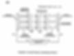
Understanding 3
Next understanding.
The primary and L2 (negative choke) are connected on one half of the "core", this gives "100%" flux transfer between the choke and Pri
The Secondary and L1 ( positive choke ) are connected on one half "core", this gives "100%" flux transfer between - choke and Sec
those 2 things above are considered "closely" coupled inductors
adjusting the core gap of the cores will adjust the ratio of charges on the plates. this is a "fine tuning" parameter for the 2:1 charge ratio.
this is considered "loosely" coupled inductors.
Answer = Correct
Understanding 4
a bigger tuning parameter for the 2:1 ratio is :
To raise the negative voltage, take turns off the L1 (positive choke) and placing them on L2 (negative choke) in order to control the charge on the negative plate. This works both ways, less on L2 less voltage on the negative plate.
We "move" turns from one choke to another to keep the impedance matching. You could also keep the impedance matching via changing the primary Resistance or doing it by adding a resistor across parallel or in series depending if its high or low.
we need to worried about resistance. more on this later but its all about impedance matching.
Answer = Correct Yes that is right, you can move turns from any coil as long as they are put back on somewhere. You must maintain the resistance in the secondary circuit in order to maintain the impedance match.
Keep in mind the Stan Meyer VIC is accomplishing two tasks in one device. You need to keep things straight in your head which task you are hoping to adjust/optimize and do it in a way that least impacts the task you already have working (hopefully).
Task 1. You must create enough amp leakage to start basic electrolysis.
Task 2. You must create a condition on the plates where there is a two to one charge ratio.
Because you are building one device that accomplishes two tasks, things become a minefield if you don't understand the relationships. One component can contribute to both tasks, so if you adjust it and you already had one task working, you probably just screwed it up.
So there is some complexity here and to overcome it, you must do things in the correct sequence which Ronnie has been walking us through. Once you get your hands dirty, it will become apparent this is an iterative process--a little adjustment here; a little adjustment there, then on to the next step.
I posted earlier the PDF about electrostatic measuring techniques. What I want you all to glean from this is in the first page or two. You will notice there is no mention of amperage, unlike what you will find elsewhere on the Internet when you search the word charge or Coulomb. It says quite plainly:
"When we move one coulomb of charge from one point to another in an electric field, we are doing work on that charge. The term we use for this is electric potential or voltage."
"Again, a volt is the amount of work it takes to move one coulomb of charge a certain distance through an electrical field E."
Voltage does do work, just like Stan said and the people that know how to measure electrostatics know this. Now you do too.
You must think about charge and the VIC as a creator and distributor of charge, charge which you will separate in the proper proportions and put it where it needs to go.
What I found very confusing to me until it finally clicked is this unbalanced (two to one) charge ratio. The reason for it being so confusing is because you have no reference point. I think you actually could though by center tapping the secondary, but suppose you don't. So what do I mean...
If you measure voltage across the two plates, you get a voltage differential. Let's say for example the value is 200 volts. Now look at this algebraically:
200 = A - B
A and B have limitless possibilities to satisfy that equation. If we add another equation:
A = 2 * B
Only then can we find values for both A and B that actually work--that actually "switch-off the covalent bonds".
We can do this because we can adjust the gap between the two cores and more fundamentally, we have complete control over what charges the VIC produces and where they go. Let's look at this closer by referring back to the image Ronnie posted.
As you can see, the primary and L2 (negative choke) are fixed on the same core. So we know immediately the negative plate will collect the maximum negative charge possible coming from the input signal. It has to because it is directly coupled. Now let's look at the positive plate...
As we can see here, the only way to get positive charge to the positive plate is to get the secondary to produce more voltage. So let's place the two C-cores tightly together so that maximum coupling is achieved. What do we get charge-wise?
Well, with 100% flux flowing through both C-cores, we can see the charge ratio between the two plates is pretty nearly one to one. You'll get a voltage differential, but the ratio is no good. This won't help us with water. We need two to one charge ratio.
Okay, I glossed over this pretty quick didn't I? I said one to one with the cores tightly pressed together. Let's look closer...
L2 is outputting full negative charge; L1 is outputting full positive charge and the secondary is outputting half-and-half, equal positive and negative going each direction. Let's forget about the diode for a moment and just think of it as a valve making sure charge is only moving in one direction on the rising impulse of magnetic flux. On the decaying side of the magnetic flux, everything just sits still because the valve opens and stops any charge movement. Hopefully now you can see one to one charge distribution when the cores are together.
When the cores are apart, again only negative charge is pushed out of the L2 choke; the L1 and secondary are no longer participating in the conversion of magnetic flux to electrical charge.
So we want a two to one charge ratio. I'm hoping you guys are already ahead of me now that I have set the two possible limits, cores far apart and cores tightly together. Now let's look at when the cores are separated apart by just the right distance...
As stated above, the L2 choke will always produce the maximum negative charge since it is stuck on the same core with the primary where the input signal is coming from. Now go slow here, another minefield awaits. What is it?
You're thinking turns ratio right? Yes, you should because the turns ratio between the primary and L2 is slightly different than the turns ratio between the primary and the secondary. Or I should say, it could be. But don't get too tripped up here and fall off the wagon. Here's another reason why Ronnie mentioned the secondary coils should all be similar turns count of similar wire. If you took heed of this, you're still okay.
Now when you bring the cores together with a small gap, the L1 and Secondary begin to kick-in their contribution to the positive charge on the positive plate. As stated above, there must be a spot where the negative charge produced at the negative plate is exactly twice in absolute value or strength as the positive charge produced at the positive plate. This is your goal--task number two. What's going on here with the gap is the manipulation of the coupling factor to achieve the desired charge ratio. I can't tell you how touchy this adjustment might be, because I haven't done it yet, but I'm sure you will want to fill the gap with some kind of a sturdy material that will not compress, so once you have things dialed-in, they will stay that way.

yes i agree, i call this the "mode change"
This is the mode where we go from starting the electrolytes mode to the resonance mode.
also on your task #2 you forgot to add that when in this mode of operation everything must match "resonance" Xc=Xl
but during Task 1 or mode 1 this is not the case.
this is why we tune the VIC with no water in the Cell!!!
( i think we understand that)
good stuff. i'm gonna keep posting things for Ronnie to agree with or disagree with. I have a few more things to post but a lot to think about still.
after i'm happy with MY understanding of Ronnie's prospective of the VIC,
then we can talk about the math. because the math and the mode go hand and hand. but it all starts with what we are trying to achieve. ( and understanding it so we can engineer it along the way!)
Understanding 5
i'm kinda jumping ahead but... lets briefly talk about impedance matching
( you already kinda answered this in the above post... but... )
keep in mined that we always need to keep a "DC" impedance match.
This is between the primary and the rest of the VIC
Sec,L2,L1,C = Pri we can say "DC" resistance.
Because its when its in resonance, that is reatance in the cap and inductor cancel each other out.
Xl=Xc, so the only thing left is resistance... kinda like we remove "impedance" the Z. impedance is normally AC resistance...
i have a follow up question on this but first... yes / no ?
Answer = Correct Yes Yes if I understand you correctly.
basically I'm asking how to impedance match.
so we know that to impedance match we want the source resistance and the load resistance to be equal.
and we know that in an LC resonant circuit... the Xc = Xl . this is dependent on frequency, at this frequency where Xc=Xl the only resistance left is the "DC" resistance. ( the wire)
so this resistance must be = to the primary. to have an impedance match.
if the primary is 10 ohms the load needs to be 10 ohms
to my knowledge that is how an impedance match works???
so that brings me to something i don't quite understand, ( a few but ill ask them one at time)
Q. we need to have the primary = the Sec+L1+L2+ resistance in the cell. correct?? ( this is of coarse at resonance) OK i'm editing this post due to the understanding of the "power matching" and not necessarily " impedance matching"
https://en.wikipedia.org/wiki/Maximum_power_transfer_theorem
i was stuck on matching the resistance, however we can fix that by looking at the link above. and the attachment in my post 2 down from this one.
Answer = use the watts-in equals watts-out power formula. This will take care of your turn ratio problem you are missing.
NOTES on Understanding 5
Using Stan's VIC and the numbers Don gave us as an example, I will attempt to show how to impedance match it all.
Question is what is the purpose of Impedance matching?
The answer is Watts-in must equal Watts-out.
Let's start with the Primary, I have already shown it has 10 ohms of impedance.
It is calculated by:
Line(Primary) side = 10 ohms
12 volts / 10 ohms = 1.2 amps
1.2 amps * 12 volts = 14.4 watts
Next we use a transformer (Amplifier) to match the Load side.
we need to know the total resistance of the load side.
Secondary side = 72.4 + 76.7 + 70.1 + 78.54 (Re) + 11.5 = 310 ohms
That is the DC ohms of the secondary, the positive choke, the negative choke, the feedback coil and the dielectric property of water all summed together.
Now that we have a total resistance of the line side of 10 ohms
and a total resistance of the load side of 310 ohms
Next we take the 310 ohms and 10 ohms and use this formula to get the turn ratio.
Ns / Np = sqrt(Zs / Zp)
sqrt (310/10) = 5.567
So we need a turn ratio of 1 : 5.567
Take the sum of the secondary divided by the primary, then square root it to get the turns ratio.
We know our line voltage is 12 volts. We can times this by the turn ratio of 5.567 which is 66.816 Load Voltage
Now we have our load voltage.
Next we calculate the load watts
using formula (66.816 ^2) / 310 ohms = 14.4 watts
Start with the input voltage and multiply by the turns ratio, that gives us the secondary side step-up voltage. Take this voltage and square it, then divide by the secondary side DC resistance. This gives us power in Watts. The power value on the secondary side must equal the power value on the primary which is easily calculated by multiplying the voltage times current. The current is calculated by knowing the resistance of the primary. Power in must match power out. This is what creates the equalibrium point at DC or simply DC impedance.
That's how you do it.
So we see there are interdependant variables here. Ronnie's approach it to fix one of these values to start with to simplify the calculations; this starting point is the primary resistance. The primary coil DC resistance must be at least 10 ohms.
If it is more than 10 ohms, then a resistor can be placed in parallel with it to make the primary resistance fixed at 10 ohms. The goal would be to wind the primary coil with just enough wire to have a solid 10 ohms.
This is the preferred solution.
When this is done, your starting turns ratio is now fixed--the ratio can be altered only on the secondary side. Also fixed is the dielectric property of water; this cannot be changed. What is left are the three secondary side coils; each of which must all have the same number of turns (and DC resistance). We will leave out the feedback coil for this exercise.
So if for example the primary has 240 turns to get exactly 10 ohms, we can deduce using the same bobbin form factor, the turns per ohm is approximately 24. On the secondary we start with no less than 78.54 ohms. We also know the turns ratio will be no less than 1 : 1.
The sum of the secondary coils will be no less than 30 ohms. So the minimum secondary base DC resistance must be at least 108.54 ohms. Using a goal-seek spreadsheet, you will find the needed turns ratio to be 1 : 4.6788.

Now as far as I know, 10 ohms is not any kind of magic number, it's just a starting point in Ronnie's method.
My spreadsheet shoots for whatever turns ratio you want and finds a workable impedance match for the wire/bobbins you physically plan to use. So you may very well end up with a primary resistance of some crazy thing like 3.587 ohms, but it will match and the watts-in/watts-out will be spot on.
Some may find this version of my spreadsheet useful or interesting. It handles primary / secondary wire of different gauges and you can adjust the bobbin parameters and exact wire specs as needed. The chart is just a baseline, so put in the numbers that match your actual physical components.
The numbers currently in there are what I am targeting at the moment. What you will notice right away is that the 78.54 Re is much larger than the resistance of the coils. Will this even work? The heck if I know without trying it.
the reason Ronnie picked 10 ohms is due to the fact that stan did the same... 10.5 ohms of wire, 220 ohms of resister in parallel = 10.02 ohms.
i need to dig in to the math a bit before i can ask more questions.
Thanks!!
HIGH VALUE RARE EXCEL HERE VIC COILS MATTS ONE
Using the goal-seek in Excel makes is possible to not have to start with a fixed primary resistance. You could spend days trying to match something up without that feature. So I'm sure that's why Stan just picked a number and worked everything forward from there. I'm also pretty sure that's why Ronnie did the same thing. If it ain't broke, don't fix it.
Also, you still have the option of connecting a parallel resistor across the primary, but only if it turns out the primary resistance is too high to match up with the secondary coils. If you start fiddling with taking turns off, you'll get things so balled up you'll end up starting over.I'm not so sure that the water in the cell will have a fixed resistance. if we start the bubbling... we change the resistance and capacitance.
so we do the calculation for 78.54 ohms????
in the end we should do the calculation for the amount of gas we want... rying to improve Stan's formula already are you. Not such a good idea me thinks.
I think this is more accurate way to show the water capacitor than what stan has given.
There seems to a great deal of research into the interaction of electrolytes with electrodes, it also seems that the capacitance is formed by a very thin layer of water molecules/ions ( only a few hundred angstroms thickness) i.e. one or two water molecules thickness, right next to the electrodes. If anyone is trying to simulate the circuit I suggest they try as per picture below, i believe its a more accurate way to visualise the water capacitor. I'm convinced its a double capacitor, not acting as a single capacitor.

@ Matt 10 ohms in the primary is critical, you have to have 1 amp in the primary. At 10 volts/10 ohms gives you 1 amp. so the target voltage in the primary is 10 volts when you hit resonance.
Because of things not being perfect the target may end up being 11 or 12 volts. If so the primary coil can still handle the amps. 12volts/10ohms=1.2amps which is the rating of the wire used. That's the reason Steven said "We found it to works better around 11 volts". Because of loses of things not being perfect.
If we use your example of 3 ohms in the primary we would have 3volts/12volts=4 amps in the primary so you can see the wire size 29 gauge is not rated for that. Therefore you would have to use a different wire size to handle the amps in the primary. Then you have to ask the question what effect would that have on the other working parts of the VIC.
We have to use the values from Stan's VIC that Don gave us in order to understand it. Even though we can change things to get the watts in and watts out, Just remember if we change things, what effect will it have on other things in the process.
Question
3 ohms/12 volts give you 4 amps.?
answer You are correct Thanks, I will change my post, it was early and I was rushing to get ready for work. It's good to have eyes looking over things, that way we can make things right when need be.
It's not to say we can't have 4 amps, We would have to work out the time constants so we would know when to shut it down at 1 amp. It just makes it more complicated and throws more spokes in the wheel.
That's one thing I always found interesting.
Even with 12V & 1.2A your only using 14.4 watts of power...And don't forget he's using a 50% duty cycle which reduces the power even more when you look at it over time.
1 horsepower is 746 watts.....I think the buggy engine was a 50HP engine. Makes you think!
I have to kinda disagree about the 50% duty cycle reducing the power even more.
When you do the math for the time constants that it takes for an Inductor (Primary Coil) to reach 1 amp it also takes time constants for it to decay. That's your pulse on time and pulse off time. (Frequency)
So in other words 5 time constants during the pulse on time will reach 1 amp, then you have an Off time of time constants for it to decay.
Keep in mind the secondary is doing the opposite, during the off or decay time of the primary is when the on time is on in the secondary, which is the voltage source on the secondary side. So therefore you have time constants that needs to be considered to match the primary going into the choke during off time of the Primary. Keep in mind we have two different voltage sources with two different amp ratings.
I see what you mean.
Still...if you can power a 50HP engine with 14.4 watts that's amazing. I wonder if Stan was able to really get 50HP out of it?All I can say is this, if he can Idle the buggy with the polarization process with that big tall cell, I can just imagine what it would do with the gas excitation process including the gas processor that also excites the ambient air.
I just can't imagine him doing all that talking about diluting the gas and adding exhaust gases back into the mix to control the burn rate, if it wasn't more powerful than gasoline.
So until the system hits resonance, the input current continues going up along with the increased voltage. And only at resonance does the current drop off.
So if there was some way to get into resonance quickly, then you could use the thinner wire on the primary. In order to use thinner wire, just close the gap up between the cells like he did in the injector plug.
We have to use the values from Stan's VIC that Don gave us in order to understand it. Even though we can change things to get the watts in and watts out, Just remember if we change things, what effect will it have on other things in the process.
Yes, this was the part a few of us were struggling with last night in the chat session. Trying to figure out what the actual process is.
Still very confusing when getting into the hardcore details. For example, the two chokes sure look to me like simple low-pass filters, but when you run the numbers for their cutoff frequencies, nothing makes any sense any more.
Mainly because it's so hard to determine what the series resistance against these chokes actually is. And without knowing the series resistance, the cutoff frequency can be all over the board from very high to very low.
So yes, a few of us are still struggling to get our heads wrapped around the methods the VIC uses to accomplish what it does.
simple question. Ronnie you wants told me this resonance is between L1 and the cell. but at some point L2 also becomes part of the resonance. could you potentially try to explain your understanding of how those things work with each other and when. This might help me and Matt think more clearly about how the chokes resonate with the cell
There is some confusion.
Yes, when Xl and Xc equal zero lets say, current is at it's max, you will never get L1 or L2 to choke off all the current from rushing back, and that causes an oscillation between the two chokes. what's between the two chokes the water capacitor.
It want be a huge amount of current because be don't have a huge amount of current in the secondary side anyway. But we do have a huge amount of voltage at this time. Just calculate the time constants of the L1 Charging and the time constant of it's decay time. You better have a pulse coming in at the right time when the decay time starts to takes place or you will have current movement.
I personally believe you will never get it to choke it all and stop all movement. That's where the term voltage stimulation comes from Stan talks about if you ask me! That little bit of current change is enough to allow the voltage to raise and lower a real small amount in the cell. (Voltage Stimulation)
If you reach this point, Just remember this old saying:
Mary had a steamboat the steamboat had a bell, Mary pulled the wrong chain and the steamboat blew all to H@$L.
So the moral of this story is, don't turn the wrong knob, or pull the wrong chain when you reach this level of resonance. LOL
Ronnie the best way I can get my head around this impeadance matching would be to compare it to a car eg first through to fourth gear we're picking up speed (L1 + cell voltage stimulation) upon reaching its max rpm engine to road speed then we select overdrive ( Resonance L2+cell+L1 begin to interact) and we have fifth gear overdrive....
Am anywhere near close?More like going trough the gears and then throwing the rocket booster on.Lol ya ok so basically getting the ratio correct.. so if the math works out how do we apply it? This is where I think we need to be able spark a spark plug and record our findings?Yes Dom. This is why we tune to a dry cell. To make sure we have it in the ball park.
Lets do the Math
Let's do the math to find the time constants on the primary side of Stan's Vic.
According to Don's measurements:
Things we need to know.
-
Primary Coil Inductance=48.5mH with core @10kHz
-
Primary Coil Resistance=10 ohms
-
Primary voltage at 1Amp=10 volts
-
First thing we need to do is convert 48.5mH to Henry= 0.0485H
-
Next we need to divide the inductance into the resistance 0.0485/10=.00485s
-
.00485 is 63.2% of the rise in current and is the first time constant.
-
It takes 5 time constants to get to a full 1 amp in the coil
-
So take .00485*5=.02425s
-
.02425s is the time period
-
Next we need to get the Frequency
-
The math for that is f=1/time
-
1/.02425=41.2371134Hz
Ok so once we get time constant on the primary do we apply the math to the secondary coils also or all we need is to know the primary??
That would be 5 pulses @ .2425 seconds each ? (time constant) to get the 1 amp
Basically we want to put this into first gear and gain movement towards the next gear?
Sure you would Dom on the L1 choke, Just remember you will have a different voltage and resistance on that side. It must match the off time of the primary. If it don't the inductance is to high or to low or the resistance is to high or to low. This is where you get into "What do I do" LOL And no that don't mean 5 pulses. It means one pulse.
Opposite Time constant but must match .2425s on time of the primary?? Am I close??
During the off time of the primary is when the secondary is ramping up current in the L1 choke, if it don't match the primary off time then you will not get all the current into L1 from the secondary.
If we have a setting we look to have on primary would that not just simply automatically covert to the secondary and L1? Would not the pulse from primary on be an off time in the secondary?
No: You want it to be, but the inductance and resistance has to be right in the L1 choke before that can happened. What's the use of having .27amps "as an example" on the secondary side if you can't get all of into the L1 choke.I will say this though, Capacitors has a time constant on them as well.
As my old saying says "Time will take care of everything, all we need is a little more time."
Let do the math to find the time constants on the primary side of Stan's Vic.
...
By using your Scope you can now measure the pulse on time.
It should have a time of .02425s
2.06 Hz ? What the...? Pretty darn slow input frequency.
Will pwm even go that slow? ;)
So where does the 10kHz come from? Is that just the core rating frequency?
10kHz is half the audible hearing range.Okay, 20 Hz then. Just a low buzz. That frequency makes a lot more sense now looking at how the VIC operates.
Just curious how many people having actually wired together a VIC, have tried an input signal of that low a frequency. I'm guessing quite a few started at the bottom around 100 Hz and went up from there..
Use these calculators, Time constants are a period of time. You have to finish out the math to get the frequency which is f=1/time
1/.02425=41.2371134Hz
http://www.sengpielaudio.com/calculator-period.htm
http://www.learningaboutelectronics.com/Articles/RC-RL-time-constant-calculator.php#answer2


I changed my post to add the extra math to get the Frequency
Quote from gpssonar on November 13th, 2016, 04:20 PM
Let's do the math to find the time constants on the primary side of Stan's Vic.
According to Don's measurements:
Things we need to know.
-
Primary Coil Inductance=48.5mH with core @10kHz
-
Primary Coil Resistance=10 ohms
-
Primary voltage at 1 Amp=10 volts
-
First thing we need to do is convert 48.5mH to Henry= 0.0485H
-
Next we need to divide the inductance into the resistance 0.0485/10=.00485s
-
.00485 is 63.2% of the rise in current and is the first time constant.
-
It takes 5 time constants to get to a full 1 amp in the coil
-
So take .00485*5=.02425s
-
.02425s is the time period
-
Next we need to get the Frequency
-
The math for that is f=1/time
-
1/.02425=41.2371134Hz
I changed my post to add the extra math to get the Frequency
1/.02425=41.2371134Hz
Ronnie, if that time constant is only the on-time, you have to double it to calculate the total period (@ 50% duty cycle), which gives you half that frequency. In this case, 20.6 Hz.
No, Matt that is not correct. that time constant is for only the on time. There is another time constant for decay time.
Well then, you would need to add both time constants together before you invert to frequency. It takes an on-time and off-time to make a complete cycle or complete time period.
============================
I changed my post to add the extra math to get the Frequency
1/.02425=41.2371134Hz
Ronnie, if that time constant is only the on-time, you have to double it to calculate the total period (@ 50% duty cycle), which gives you half that frequency. In this case, 20.6 Hz.
No, Matt that is not correct. that time constant is for only the on time. There is another time constant for decay time. Well then, you would need to add both time constants together before you invert to frequency. It takes an on-time and off-time to make a complete cycle or complete time period.
Matt the time on is the same as the decay time which gives you 50% Duty cycle. Just double the 4Hz Frequency. Only thing different in the decay time is, it decays down to 38% instead of 63% rise but takes the same amount of time.


Yeap. I mostly expected that. The primary diode forces the back EMF to turn around and re-enter the circuit and the WFC just soaks it up--the energy has nowhere else to go.
And by the way everyone, you can calculate these time periods or use an amp probe on your scope so you can clearly see the charge/discharge cycles as you adjust frequency.
Big inductors like these at low frequency typically show a textbook response--just like Ronnie's images above. You can also use a CVR (low ohm, non-inductive resistor) placed in series with the primary, then connect your voltage scope probes across the resistor.
I have a 0.1 ohm and a 0.02 ohm that I use often for this. The smaller the better because you don't want to mess up your impedance match.
You'll find it interesting to put it in series with the transistor output and then put it in series with the primary, the later way you can see the back EMF (recoil) surge back against the diode.
All good information
Can you clarify - vic must produce 2:1 ratio charge. You wrote in answer to Russ more B+ voltage.
Are you mean vic must produce 2x more positive charge than negative?
andy don't read to much into the 2:1 ratio. There is more to it than a 2:1 ratio
Can you tell - vic must produce 2:1 ratio charge. You wrote in answer to Russ more B+ voltage.
Are you mean vic must produce 2x more positive charge than negative?don't read to much into the 2:1 ratio. There is more to it than a 2:1 ratio hope its 1.4 x more turns on + or.7 less on -
Ronnie
You wrote this:
He tells you exactly what I have been talking about how to switch off the covalent bond of the water molecule.
Notice the two hydrogen and one oxygen and listen to him.
He uses the voltage on the B+ to switch it off. Question is how does dial in the B+ voltage?
What set of cores is the B+ on?
Would the Gap of the two cores adjust the fine tuning of the B+ voltage?
You know now that the two hydrogen atoms will place more charge on one plate than the one oxygen atom will due to cancel of charges.
You should know how to raise the B+ voltage by taking turns off the L2 and placing them on L1 in order to control it's charge on the plate and how to fine tune it with the Gap of the cores.
end quote
I understand from this , that we need the twice more positive charge on B+ plate than on B- plate.
Is this correct?
=========================
If we use your example of 3 ohms in the primary we would have 3volts/12volts=4 amps in the primary so you can see the wire size 29 gauge is not rated for that. Therefore you would have to use a different wire size to handle the amps in the primary.
And I have a fix for that...
I can use thicker wire with two bobbins. One bobbin has the current amount of turns needed and this bobbin is placed on the core as the primary. The other bobbin is wound until the total ohms is matched and this bobbin is left off the core as an air-core coil.
And we're back in business. No burns, no errors, no problem.


This would probably be some good wire to have on hand for this project:
https://www.temcoindustrial.com/28-awg-copper-magnet-wire-5-lb-mw0216-magnetic-coil-gpmr200.html
Dielectric strength of 10,000 volts per layer should be about right.
When I use this wire and run the numbers with my cores/bobbins,
I get pretty close to Ronnie's values:

I have two scope shots showing the output charge ratio in action here.
The schematic depicts where my reference point is.
Yellow trace is B+; blue trace B-
You can clearly see how B+ is twice the voltage of B-. This should be rather obvious since L1 and the secondary are connected in-phase so the voltage from each adds together. L2 is out-of-phase and shows reverse voltage.
The final scope-shot I found rather interesting. It is with a cap connected across B+ & B-. Take a close note at where the left-hand tic mark is for the zero reference point of the B+. The cap is never completely discharging to zero as we would expect the WFC to do also. Granted, the dielectric properties of this cap is much different than that of water, so you can probably guess this VIC is not tuned to it at all, but if it was, can you imagine how the voltage would increase until the cap exploded somewhere above 6000 volts...
Now some might ask why I'm not hitting high voltages here. The main reason is because I'm only driving this VIC with a low power signal generator--I'm not throwing any serious amps at it at all. The core is miles away from saturation. Those spikes you see are the change in flux over time; most of which happens in the first few milliseconds.
This change would be far more intense if I was using two amps instead of 200ma and the voltage rise would go up proportionately. With a quicker and higher rise, the frequency could also be increased, which translates into more power in less time, leading to higher charge levels.
Once you get to a point where input power exceeds leakage, that's when things take off to infinity.


Sounds good Ronnie. Making progress, but it's sure easy to get myself screwed up.
Speaking of screwed-up, I had my L2 wired backwards. Easy to do. Looked right at the schematic and did it wrong.
So with that fixed, have a look at how this thing functions now. As you can see, L2 does not add to L1 and the secondary, it subtracts from it. This is how we get the proper charge ratio. Charge is absolute between the VIC and WFC, but relative to the rest of the world.
So this scope-shot shows the VIC charging a capacitor, depicted by the purple math trace. Notice how now the B+ and B- waveforms are no longer altered by having the capacitor connected. I also have the duty cycle set way down to conserve input power while still providing a strong impulse.
You might ask why does the B+ and B- appear to have the same voltage peaks. L1 and the secondary combined are twice the turns ratio, meaning half the amperage capability. This allows the L2 to over-power them amperage-wise, which pulls the voltage down to the same level as L2. As you can see though, I still have 40+ volts to start the electrolysis process and form a few bubbles. Once the amp-leakage is overcome, then things should start to get interesting...
Hey Matt, just a guess here....that's not an electrolytic cap you used was it?
No, it's a 6000 volt ceramic, 0.001 uF. Still don't know the best way to simulate an actual WFC.
there are options but who knows whats the best
https://en.wikipedia.org/wiki/Nonlinear_element
transistors use feedback to get a more linear response....brilliant
This cap provides enough load to keep voltages manageable with the scope probes I have
All I know is ESR of electrolytic are much higher than ceramics if that matters.
yeah adding a resistance is the best you can do.
Good first tests all in all you got to try.
I hooked-up a decent driver and put about 5 volts at 1 amp to it. It started making a few real tiny bubbles in a little single cell I had laying around is all. No matching or anything done yet, just point and shoot and see what sticks.
Pretty clear to me the charge ratio is well out of whack, but at least it's all together doing some semblance of a Stan Meyer VIC.
I'll scratch my head for a while and see if I can think of what the proper adjustment(s) should be..

If you had to make 100 VIC's would you use the Stan Vic or the duel core?
Stan's Vic if I were building a 10 cell unit
i think its important that you try to tune the system with a value of resistance/capacitance where the cell is, if you try ti with a dry cell ( as Ronnie states) it might work... just using the air resistance. however i have a feeling that if your making lots of gas the resistance will not change as much as you think, at least i feel it will not get as high as a cell with no water. but the charges play a lot of interesting rolls and things we dont understand.
i would suggest you use a Variable cap and a Potentiometer both in the ranges that the WFC will be,
for testing it might be helpful, I'm not sure. maybe we should just use a cell. but it will reveal some new results to think about...
oh by the way that charge ratio with a cap only Vs the cell, i think you will not see those ratios get back to 2:1 until you really start making gas. and even then i have a feeling there will be a lot of resistance, (more than an air cell) but at that point you tune it in... thats why the step tuning process is so important WITH THE CELL connected.
at least you seen a few bubbles. thats already good news. This proves that if you tune the cell to a 2:1 with a cap or dry cell, you have enough offset potential to start even a little electrolytes. ( your sending in AC so AC dont make gas) so thats a step in the right direction if you ask me...
you might not be able to measure the 2:1 now with the "dead short" but its there, those bubbles prove it. but its a resistor... so think how you measure that...
oh what traces are what on your scope there?
-
Yellow is B+ to reference; blue is B- to reference;
-
Purple is math difference between the two.
-
The B- trace is AC since you can see on the schematic there is no rectifier diode on that side. B+ has the rectifier diode and is mostly DC--offset from zero.
The math trace is clearly all DC--that is what the cell is actually seeing.
What I may do next is connect a current probe just to get a feel for how much current is hitting the cell, then check the cell resistance.
I'm curious to know if it is the cell over-powering the VIC or the VIC over-powering the cell.
I really don't dare run things with the cell open (no water) at this time using the driver and only 10x probes--pretty sure the voltages will shoot up too high to deal with.
Maybe if I keep the power supply way low around 2 volts I'd be okay for quick peek.
Maybe if I keep the power supply way low around 2 volts I'd be okay for quick peek.
yeah keep it really low. besides the core saturating,
everything else should show the same transients


Ronnie what did you use on J input analog voltage?,
i think you used the digital means board but we don't have that..did you know a cheaper way?
i used a pot.but the voltage level did go only 9.45v
Stan's variable voltage going to J is only around 10 or 11 volts, 9.45 volts will work just fine.
is it possible to use high dielectric transformer oil........... :D
So put the whole VIC inside a oil bath??
I wouldn't think this is necessary unless you can't find any wire with fairly high-grade insulation, but...
You gave me a great idea for finding the capacitance of a multi-plate cell.
Transformer oil would provide an excellent dielectric to fill a cell with and get some accurate readings when you're not sure of the exact surface area or spacing.
Looks like the dielectric constant is 2.2.
http://www.engineeringtoolbox.com/relative-permittivity-d_1660.html
But how would you get all the residue out of your cell afterwards? If you know the value of water at a certain temperature and purity the clean up would be nonexistent.
That is why i thought that chart i could not load but you did for me would allow you to further nail down the parameters you need. Because it is from 0 c to 100 c temperature range.
Or are you questioning its accuracy value wise and that is why you prefer the transformer oil?
Its Snow Bitches
The dielectric constant of snow in the RF band may be more practical :)
Maybe even a frozen cell with ice would be more in the ballpark at least for a period of time, phase or level of the process.
Makes me curious how even dry ice pressurized in a cell would simulate a level of it.
Endless ideas and points to make...even for instance a flushing cell may simulate to having ozone bubble up through the water.....ideas ideas ideas :0)
" The dielectric constant of a water molecule is dominated by the reorientation of the molecule due to its large dipole moment. H2O is anisotropic and, because it crystallizes in a hexagonal system, it is considered uniaxial..... "
" Go ahead and put snow in there"
"WHY IS SNOW WHITE?" Stephen Meyer
Ozone is easy enough to produce. Just filter air through a desiccant first there was one of Stan's patents that hinted to ozone.
if anyone is worried about coil integrity of insulation. Once you finalize the coil wraps, just get glyptol and either spray layers or dip coil and bake it with multiple cotes. It will help restrain the coil from moving much like they do in electric motor shops. Plus it adds more insulative quality.
Mr. Ronnie or anyone else out there. What is the effect on the coil if an external wrap of aluminum is placed around the coil? Will it affect the flux lines on coil in a more dense way?
Does it change the timing of the collaps of the field? I have not wound any yet to try and see effect. Just hypothesizing for now. I have foil tape that is does not hold lines of flux like iron does but it does relate to lenze laws.
NOTES on Understanding 6
There are things that people still need to know about the polarization process before we move into the other areas of the process.
This is a two part process.
Part 1
Most people don't know the L1 choke, with Direct Current the coil has no inductive reactance.
There is a reason there is an offset voltage.
It's to get the process started and never let it fall below that voltage level.
Part 2
If it falls below that level you will lose the polarization process. So in other words as soon as you turn the unit on, it starts with a DC offset voltage and the process starts. Again the L1 choke coil has no inductive reactance with Direct Current.
It's an RC circuit well before it becomes an LC circuit.
I say it is a two part process because the RC circuit sets up an environment of an attracting force between the two plates to align and stretch the water molecule (Polarization Process).
Then the LC circuit kicks in at a predetermined voltage level in an instant of time and sets up the repelling force on the two shared electrons that holds the water molecule together,
Like Stan said
"with enough repelling force on the two shared electrons the water molecule just falls apart,"
(Like a light switch cutting off the covalent bonds that holds them together).
That's what the VIC (voltage intensifier (CIRCUIT)) does.
=========================
Guide me if my instincts are correct…
If you DC bias the primary, you have the ability to push that half of the core into saturation where you can modify the behavior of the L2 choke. However, with a gap between the two core halves, the tendency to also saturate the other core half is much reduced, so what happens to the L2 doesn't happen or happens much less to the secondary and L1.
And why would anyone want to do this…?
I have been thinking about this question a lot. Seems to me we have created quite a conundrum by having the L1 and secondary on the same core connected in-phase while the L2 hangs out there all alone on the secondary side.
As I see it, the L1 and secondary are working together as one big coil with a much higher combined turns ratio than the L2. So we have more volts, but much less amperage to speak of. So compared to the L2, how do we get the amperage up to about equal on the L1 and secondary?
Answer. We don't.
Instead, we drop the amperage on the L2 without changing its voltage much, by introducing a DC bias to that particular core.
If we do it right, the B+ and B- current flow will the equal (from the reference point) and the differential between these two points will become zero--no current flow between B+ and B-, while still maintaining the two to one charge ratio.
That's my thinking anyway and I say this because it appears to me in my current setup, there is current flow between B+ and B-, which is why my L1/secondary voltage looks knocked down by the L2.
It looks that way because the L2 is actually overpowering the other side and pulling it down towards B-. If I'm right about all this, adding the correct DC bias along with the proper core gap, should fix the problem I'm seeing.
I'm looking at my stout Amorphous C-cores and I can tell you this much with surety: I'll never hit saturation with these cores using the input power we are targeting.
I think this is why Stan chose to use those non-standard thin ferrite cores. One half of this core would be relatively easy to put into saturation with just a small DC offset.
Find those thresholds to reach infinity voltage (if electronics would permit). You got it.
Side note for those studying
LC/RC circuits could be found in all audio applications.
Low frequency harmonics, bass frequency, are cut with a high-pass RC filter. The opposite is true with an LC low-pass filter, cutting out the high frequency harmonics, treble frequency, both at a specified cutoff frequency or threshold. Generally called a band-pass filter.
What happens at the cutoff frequency? Between being an RC and LC circuit... is that the resonant point?
We may be capturing high frequency harmonics, BEMF, in an LC circuit setup, and orient its energy via high-voltage diode.
ANSWER: he DC bias is only a potential difference of 1.23 Volts. Just so everyone don't make a mountain out of a mole hill.
EXAMPLE: Hydrogen electrode -0.41 volts Oxygen electrode +0.82 volts.
Do you mean that many different cores will work with the help of the DC bias on the primary?
It looks to me like if the cores are too large, any DC bias you provide may not have the desired effect. I think we need to back up a little and determine what the DC bias is really trying to achieve, it may not be what I described previous.How you realize in practice the DC bias on the primary?
I was eating turkey and could not stop thinking about these numbers.....
At 1.8V on 1 cell (smalll gap) we would be making HHO...That’s what I do.
At 2V we would be making lots of HHO but wasting current.
At 1.23V we would be making some HHO? but current would be very low.
Why did GPS use these numbers?
Are these the numbers used in the so called the polarization process?
hose numbers means a lot whether you know it or not. I don't care if you got one cell or five hundred cells.
How many of you have charged up a cell and disconnected the cell and hooked up a led across the cell and watch it stay lit for a period of time before the cell completely discharges.
Everyone ask yourself why the cell will lite the led after the cell has been turned off?
I'll give you the answer, the water molecules are polarized which will keep a charge on the cell and the led lit,
once they lose there polarization they start to spin again and the led dies out. It takes a potential difference of 1.23 volts to maintain the polarization process.
If not you will have to start the process all over again from the start.
I think most any core will work if you can fit the large bobbins on it. If the core is very large the VIC will tune ln at a lower Freq.(we really don't want that)
I bought my core from
Amazing1..I had to call and ask for the largest core they have and paid to much for it.
Edit...I just checked and the core I have is 3.48 x 3.65".OD window=2.46 x 2.4
It's is a little small and was hex shaped but with new bobbins it should work.
http://www.amazing1.com/transformers-high-voltage-high-frequency.html
I just wish we could get the IF core..it gives room for the sensor coil and off the shelf bobbins will fit
THE CORE MUST BE RIGHT
Looks like you realized too,that the biggest problem is the core.We can make theories all day long but without a good core and technical data we will spend 2 more years theorizing about how it might work and wind coils on what we find laying around
http://www.tme.eu/ro/katalog/miezuri-de-ferita_112517/#id_category=112517&s_field=artykul&s_order=ASC&visible_params=2%2C42%2C74%2C139%2C236%2C459%2C1362%2C1382%2C1382%2C1729%2C1730&used_params=1382%3A373465%3B
U93/76/16-3C90 i think is the closest on ,they ship around the world but we have to all agree on one to have similar results I tend to agree It looks to me like, not just any core will work.
The DC bias on the primary changes a lot about the interaction of the two C-core halves.
this core might work it's nice and large but not super fat-15-16mm.
DO NOT GO TO THEIR WEBSITE (IF-CORES.com) Google says it's not safe.
We could fit off the shelf bobbins on it from Cosmo or make some.
The Rub is I dont trust this guy..2 sales in 5 years on Alibaba?
Who knows if this part is for real or a PIC from 1999?
Alibaba link....safe
http://ifcores.en.alibaba.com/product/453592104-209712281/ferrite_core.html
Pretty much, with just one little caveat that I never heard Ronnie mention as yet...
Y'all recall the formula as Stan presented it in his Tech Brief correct?
Those R's and Z's are different for a reason IMHO.
The R's are fixed regardless of the environment they are subjected to; the Z's are not. They can (and will) deviate dependent upon frequency, phasing and wave reflection.
This is the reason, again IMHO, the VIC is designed as it is--too make the formula remain balanced through its entire operating range, i.e. through all the stages required to fracture water and make it a usable fuel gas. Look at Eq. 8 carefully.
You will notice if the chokes are not designed properly, the characteristic impedance will drift radically away from the DC resistance.
It's this DC resistance we calculated for way back in this thread that we are trying to stick to, but if the chokes drift, the formula is a bust.
LC circuit Impedance = C + ER + voltage pulse-frequency;

Throwing out my opinion here some more...
It is my belief there is no such thing as resistance (a fixed value); everything is impedance. This is what is really happening in an electronic component known as a resistor. It is also what is happening in a mechanical device known as a critical orifice. We perceive it as fixed because it does not change over a wide operating frequency, but it really functions internally as an impedance device, just as John Shive demonstrated in his wave machine.
This brings me back to the VIC. My gut feeling is that Stan was looking for high inductance chokes/coils that were as close to air-cores as he could get while still having some sort of a core that would direct the magnetic field, i.e. provide flux coupling.
This coupling is as tight as possible between the primary (exciter) and L2, while being loosely coupled between the primary and the other two coils.
Tight coupling is also needed between the secondary and L1 to keep the mutual inductance as high as possible.
Somehow (still thinking about it) this design creates a situation that optimizes the usable range of the VIC so that it can track the changing dielectric property of water from 80 all the way down to 4. Nothing else can do this over that full range.
What I'm getting at is that Stan could see the equation needed and found a way to keep it balanced over the range he needed to manipulate the water molecule and its wide dielectric property range.
Frequency is only part of this control mechanism; the water itself is the other.
The idea though is to use components that act as nearly fixed values (resistors).
By doing this, you don't create holes in the equation--meaning the formula stays operable through the whole range from 80 down to 4.
If your design has any dead spots where the impedance drastically changes, you can't push the water through all of its stages. You'll get stuck and never produce any gas.
This brings me back to the VIC.
My gut feeling is that Stan was looking for high inductance chokes/coils that were as close to air-cores as he could get while still having some sort of a core that would direct the magnetic field,
i.e. provide flux coupling.
If you "increase the turns on the secondary and [both] chokes, more voltage can perform work." @ 15m57s
hat I'm getting at is that Stan could see the equation needed and found a way to keep it balanced over the range he needed to manipulate the water molecule and its wide dielectric property range. Frequency is only part of this control mechanism; the water itself is the other. The idea though is to use components that act as nearly fixed values (resistors). By doing this, you don't create holes in the equation--meaning the formula stays operable through the whole range from 80 down to 4. If your design has any dead spots where the impedance drastically changes, you can't push the water through all of its stages. You'll get stuck and never produce any gas.
With no or nil turns, no work can perform.13:23 (180 degrees out of phase)
I've said it in my other thread. It's all about stripping electrons form the water molecule. The water molecule will not fall apart unless you equal the force that holds it together. (Period)


Ronnie, can you give us any advice on tuning and finding resonance?
I just did in my last post. You can under charge the water molecule and you want have enough attracting force to strip electrons, you can have to much force and you end up with a repelling force.
That's what Stan means by tuning into the properties of water. Watch this video and you may get something out of it.
1) Why didn't Stan use three identical self-inductance coils S, L1, L2 on the "secondary" side of the VIC?
2) Why does the S coil have the smallest self-inductance?
3) Why does the L1 coil have the largest self-inductance?
Since the "secondary" side is one coil split on three. S, L1, L2.
How to choose the S self-inductance (or number of turns) of the coil...since they are all series connected...The conclusion of which should indicate that we must hit the proper balance of charge--these are not real values; instead, they are integers. Can anyone say "step charge" ?
If people can't wrap their head around Coulombs Law, they just as well lay the Vic & Cells down and let them collect dust. It answers all the question needed to build the VIC and the Cell to do what it's suppose to do.
(Break the Covalent Bond & Strip Electrons) You even have to know this to build the VIC & Gas Processor as well. (To strip the electrons from the oxygen atom).
I tried to walk everyone through Stan's Vic to get to this point so people would understand the working parts of the VIC. Maybe it's best if people starts at the water molecule and work backwards on this using Coulombs Law. It should answer all the unanswered question for everyone about the Cell and Vic.
I thought you need to add the D dielectric constant of the water in the formula.
F = (k . q1 . q2) / D . r2
~webmug
Here is a Coulomb's Law Calculator.....
Shows the force in newton's... Don't know what it means.
http://www.endmemo.com/physics/coulomb.php

As we charge our tube sets beginning at 2 volts at the primary and increasing in equal increments of 2 volts (to max 12 volts),
we should be able to record corresponding equal incremental voltage increases
(stepped up voltage according to the windings in the VIC) in the charge at the fuel cell.
Once the cell is fully charged:
1. it should remain charged like a capacitor even if we turn off our primary circuit
2. we should then be able to switch on our source voltage at max 12 volts,
at resonance, and between gated off intervals, we should see step charging occur as equal incremental voltage increases that yank away at the covalent bond in the water molecule quite vigorously, producing HHO.
3. i would expect that after initially charging the cell, and turning off the primary,
the voltage level would drop a bit, but then hold steady.
4. i would expect that once we again switch on the primary at 12 volts, the cell voltage would increase.
5. the resonance of the stepped up voltage is the workforce, but because the cell is already charged,
there is very little amp draw needed to initiate and sustain gas output. 6. 4 to 6 ounces of gas pressure in the cell stabilizes the capacitance therein.
========================
Simple Question,
Do YOU think that the cell when there is charged
( alignment of the water molecule) that it acts as a diode?
aka,
"The most common function of a diode is to allow an electric current to pass in one direction (called the diode's forward direction),
while blocking current in the opposite direction (the reverse direction).
Thus, the diode can be viewed as an electronic version of a check valve. This unidirectional behavior is called rectification, and is used to convert alternating current (AC)
to direct current (DC),"
https://en.wikipedia.org/wiki/Diode
yes its going to behave slightly differently.
But if we can hold a charge in one direction using a tinny offset voltage ( current) then "tap" it with higher pulse frequency. then we can get resonance between the cell and L1 and the cell and L2.
these are some random thoughts and just want your thoughts on it. it may be way off track and thats ok, i wanted to ask Do YOU think that the cell when there is charge ( alignment of the water molecule) that it acts as a diode?
=======================
Today I was using the scan function on my frequency generator. The freq gen scans in .01Hz increments at about 1Hz per second.
Still no luck finding resonance so I decided to look at the bandwidth of the circuit. My VIC is very close in values to Stan's. Doing the math I found the circuit has a bandwidth of 28Hz. I plotted the frequency response graph and quickly realized somewhere I'm missing something....If the bandwidth was really 28Hz I could find resonance easily....
I am thinking the water capacitance changes when you apply voltage to it....If so this would make the frequency response extremely narrow....And it would mean that the resonant frequency will change with voltage amplitude???
Sort of like an edlc (electric double layer capacitor).
Ronnie, can you verify if the resonant frequency changes when the applied voltage to the primary coil changes?
yes it dose, that's why Ronnie specified 2 things,
1. tuning with a dry cell first. ( removing a lot of variables) if your in the ball park you should smell ozone
2. tuning in 1-2v increments.
also, for fun, if you seem to find a resonance around 28hz,
try adding a 7th harmonic frequency on that single ... or any higher level harmonic.
the very early pages of Stan Meyer's Water Fuel Cell Technical Brief (section 1) defines a lot of basic parameters of the 'pulse forming network'. Page 1-2 indicates 'The value of the Inductor, the value of the capacitor (ER), and the pulse frequency of the voltage being applied across the LC circuit determines the impedance of the LC circuit.
The impedance of an inductor and a capacitor in series, Z series is given by
Z series = (Xc - Xl)
Where Xc = 1 over 2 pye divided by LC - and - Xl = 2 pye multiplied by fl
When i read that about a year ago, it seemed clear to me i have to build the cell first, measure the capacitance (dry and wet - at least), and then build my VIC impedance to match the capacitance of the cell.
Because i can measure the resistance in a winding by the wire length, but how do you measure the capacitance of the cell until you actually assemble the cell?
I don't know if this is relevant to all of Ronnie's work and teaching here - but it just seems to me building the cell first gives us constants with which we can complete the formulas for the inductor circuits -
we then have some constants in the formula - primary voltage/amperage/frequency variables - and cell capacitance.
If the cell capacitance is unknown - how do we match the impedance?
You can always go from physical dimensions of the cell(s), to capacitance this way:
http://hyperphysics.phy-astr.gsu.edu/hbase/electric/capcyl.html#c1
The tricky part is considering this "capacitor" is also a wave guide, but at what frequency is it trying to guide? The dielectric of which, determines the velocity factor. And we know the dielectric can change from 80 clear down to about 4. So with a fixed size "capacitor" that has a variable dielectric, what value do you want to shoot for? Then how many of these cells do you want to put together in series?
Now suppose you have all the above figured out and you're ready to mate a pair of inductors to it. Again, what resonant frequency do you want to shoot for? Maybe a harmonic or maybe the fundamental?
And lastly, how does this all fit in with Coulombs Law? Because if you recall Ronnie's statement, if you don't comprehend Coulombs Law, there's no point in going any further.
Hit a wall yet?
This is why a strategy is needed.
We need a fundamental principal in effect that guides all the rest of our decisions in building a VIC & WFC. My current thinking is to look at the VIC as a low-pass filter that allows charge to flow through it and get to the WFC in the correct proportions.
And as a filter, it stops most of the current flow, but not all of it. We need a little for the initial 1.23 volt per cell charge and polarization process. This filter also redirects any reflections coming back from the WFC, puts them in-phase and resends them back to the WFC to create the resonant-rise condition.
This is how I look at the VIC. It may be completely wrong, but until I hear the correct & complete method of operation that I can actually understand, I'll stick with it.
My feeling is that the water molecules, the electrons and all that deep stuff must be manipulated just a certain way.
You can't just go hitting it with any ol' signal and expect results. If you do, the water will simply reject the signal and send it right back to you, potentially burning up your coils. A properly designed and built system puts just what you need at just the right time. It's an analog computer built specifically to split water.
Simple as that. And being an analog computer, it can respond instantaneously via potential and at the speed of light via kinetic energy. So gigahertz signals and terahertz charge potentials between the VIC & WFC are entirely possible. Keep in mind you are trying to control the electron clouds around billions of water molecules. How fast do you really think you need to be?
Yeah, pretty fast.
I think your the only person I have seen mention the velocity factor. Glad someone else has looked that deep (I'm sure Ronnie has also).
As you probably already know, the dielectric of the water reduces the velocity of the em wave by a factor of 8.89 (if I remember correctly).
I did this math a while back and noticed there may be a connection between the velocity factor and the total length of the vic circuit- close to 1/4 wavelength but since it was the length of all coils I'm not sure if it's contributing or not.
One cell of mine measures 18pF...Come on guys show your cells and measure them for real not make theories about how would it measure
Post real numbers not fairytales...
Besides Russ no one showed what their measures empty...when posting real numbers then we can compare our setups and find mistakes...for example i was rambling some time ago about why my primary had 3.2mH(air core) with the same wire and wire lenght
Stan had and the same meter Fifth Colum uses for measuring...no one answered...to find this out i had to buy another 100$ meter + 150$ 29 gauge wire from US mine was 28 gauge to find out that was the same..
Stan's primary was 1.65mH Ris
comparing to a different number which was wrong ,
you probably too good wound up your primary winding
or your meter remained at a high induction readout
Links
https://th.aliexpress.com/item/738236533.html


Description:
Relative products on the market, inductance meter capacitance (eg 6243 series) in a small scale, the test value is indeed useful as the accuracy and minimum resolution, and has a flexible calibration cable, the measurement accuracy can be maintained at any time, the instrument does not use any meter to adjust the calibration parameters. Are completely stored in the internal flash microcontroller, wont be lost if power down, more accurate and convenient calibration with other potential methods.
property:
-
Brand new
-
Model: LC200A
-
Power supply: + 5V, mini usb interface, 4pcs AA batteries
-
Measurement accuracy: 1%
-
Capacitance measurement range: 0.01 pF-10uF
-
Minimum resolution: 0.01 pF
-
Big capacitance measuring range1uF-100mF / Minimum resolution: 0.01uF
-
Measuring range inductance: 0.001 uH-100mH
-
Big inductance measuring range: 0.001 mH-100H
-
Minimum resolution: 0.001uH
-
Test frequency range: L / C about 500KHz / Big inductance 500Hz
-
Effective display digits: 4 digits
-
LCD display mode: 1602
note:
-
When measuring the frequncy of inductance or capacitance, please press the black button as the figure showed.
-
Pls reset zero, before testing capacitance or inductance, or it may damage the board.
-
If the result on the LCD is not stable, it's normal due to the poor quality of L / C.
I have an insulated 6 cell unit similar to Ronnie's.
My cell measures around 180-190pF with distilled water.
Russ,
This is where I run into problems.
Do the math and you find out my cell dry is around 2.1-2.3pF. It measures 2.11pF.
At 2.1pF and with a 1.262H choke resonance is 97 kHz.
At that frequency the reactance is 769k ohms..
Say you hit resonance, if the voltage across the secondary coil were 2V we know the resistance is around 220 ohms.
This gives us 9mA current. 9mA @ 769k ohms will produce 6700v.
The problem here is the coil has about a 1:7 turns ratio so the primary coil would have to be pulsed at 289mV.....
My frequency generator cannot produce a decent square wave at those frequencies and my drive circuit does not work well at amplitudes that low.....I need to find something else with similar capacitance as my cell when it's filled with water?
Update: I tried a fixed capacitor which has 390pF. Still unable to hit resonance.....very frustrating....
Something is wrong somewhere in my circuit or vic???
VIC values:
Primary 9.9 ohms. 44.3mH SECONDARY NEED TO BE INSULATED AND SEAL WELL
Sec 69.2 ohms. 1.205H
L1 73.2 ohms. 1.168H
L2 67.2 ohms. 1.054H yes no pick up coil in calculations lol EASY mISTAKE
PICKUP COIL
If you shunt the diode, do you still see a lack of resonance
Your right....
I took some time away from it and thought about what might be going wrong. I went back and measured everything again and did the calculations. Turns out I need to make a few adjustments to my coils and drive circuit.Just something to think about. there WILL be higher frequency with in that cell. so its hard to say weather or not a low F input will be some harmonic of the resonant F that might be a lot higher.
i see that you updated your findings, any chance you can tell us what was " wrong" that you fund?we can keep an eye on it for our own set up too?
Stan never hide it Matt. It's in these drawings and others as well.


found my drive circuit was going below 0V.
Also, I'm not sure but I think my choke values were not right so I made some adjustments to the coils inductance values.
Gunther,
In one of Stans last news releases he explains particle oscillation as if it were the key to the whole process. We know accelerating charged particles produce em radiation....I have done a lot of reading on electric double layer capacitors....In some cases they exhibit oscillation and em radiation
My two cents...
GPS has talked about impedance matching for weeks.....
I have to wonder if we are trying to get standing waves to stand on the cell with a 2-1 ratio
and a DC offset.
well lets get back to "checking my understanding"
Ronnie, This is directed to you, got some more Q and A , if you see ANYTHING you disagree with please state so.
If some of this is a repeat, just answer it any way. please answer yes/no for each number. or reword it to make scene to you.
1. The chokes are indeed amp restriction devices, using the magnetic flux,
However Because the Capacitor is "variable" ( due to the gas bubbles being formed) the "bandwidth cut off" of the resonant frequency is out side the parameters needed to achieve resonance between L1,L2 and the "cap" .But ONLY when in the "dead short" condition is there. YES CORRECT
2. The change in capacitance/resistance will allow the resonant action to take place. its important to note that the chokes do not enter resonance until enough gas is generated to change the capacitance / bandwidth cut off to do so, this is automatic and by design.
(this must be part of your design. parameters) YES CORRECT
3. This is why we need to tune the system with dry cell's, This is how we check the resonance of the system.YES CORRECT
4. Resonance only happens when we reach that sweet spot after we start making gas ( after the start the polarization process with our amp leakage) and if the bandwidth cut off allows to go in to resonance.
YES CORRECT
5. Then things change when in resonance mode
( The phase angle changes between current and voltage when things change in to resonance mode.)
YES CORRECTand I got more to say about this in another post.
6. This is a Question: we can change the phase angle changes between current and voltage
by having an imbalance of turns between L1 and L2???
:got more to say about this one as well in another post.
The voltage phase angle is 90 degrees opposite to current phase angle, at resonance.
Leading or lagging?Interesting.
With strictly pulsed DC currents, or should I say voltages, this would also leave a strictly reactive circuit, with inductive reactive components acting as short circuits, capacitive reactive components acting as open circuits and as it's 90 degrees the resistive contributions could also be considered to be open circuit.
Would this be a good parameter to check out (I.E the phase shift between voltage & current in say the secondary coil) to sort of "home in on" while tuning cell frequency....?In the
TB Stan states voltage leads by 90 degrees.
So at resonance it's an inductive circuit.
Successful testing will have to be done to confirm it though.
"And, as the voltage will now go through this [choke] coil, 90 degrees opposite to current, and as a result: we have a way to pull apart the water molecule in an economical way." aka. resonance.
This is mentioned in Stan's lecture @ 15m55s:The RLC circuit must produce this condition: progress towards a voltage phase angle 90 degrees opposite to current phase angle.
I hypothesize the bandwidth cut-off frequency in the RLC circuit is your resonant frequency.
The RLC tank acting as both a high-pass filter (cutting out bass) and a low-pass filter (cutting out treble), typically a band-pass filter in the audible frequency domain, from 1 Hz up to 24 kHz (the range of frequencies we can hear with ears).
I hypothesize if both high- and low-pass filters are by design and active in the RLC/VIC circuit, you'll only have one sinusoidal output, which could be your resonant frequency to achieve. The filtered energy is redirected through.
That's what I would have thought too. In the video Dom posted above, valyonpz sweeps the spectrum with just the cell and a resistor and we see all sorts of characteristics. If I'm not imagining things, I'm pretty sure I saw both leading and lagging. I also saw DC offset appear. I have a hunch this is something each one of us should try with the cells we have.
I would highly recommend using a very small (< 1 ohm) CSR (current sense resistor), or you will get data that isn't very useful. I would also recommend repeating the tests using a voltage range between 1 and 13 volts, with and without a 1.23 volt DC bias per tube set. Be thorough, plot this data and keep it with your cell--I have a strong feeling you will be referring back to it many times. Also, fill your cell with the same water you will likely use if/when you ever get your VIC working.
sounds like a place to start. ill make that my first step when i get everything set up.I'm saying that this self resonant test is only good for a wet cell...
unless you plan on doing the test dry?Wet for sure. I think a dry capacitance measurement is probably enough and just a rough estimate at that.
So Russ,
I'm modifying my Bob Volk Hybrid cell and I need some hard spacers that are about 1.5mm thick and can be secured to the face of the stainless steel plates. Can you think of anything readily available that will work?
And another dumb question that I should already have the answer to but don't: The resonant cavities--do they allow water fill only from the top or can water come up from the bottom? I need to decide if I should plug these re-fill holes off or not.

valyonpz's videos look like he had recent success.
https://www.youtube.com/user/valyonpz/videos
hate to complicate things, but Valentin used a 22 ohm CSR in series with what I will assume is a 50 ohm output signal generator. That's 72 ohms--pretty close to Stan's 78.54 Re value. If it were me (and it will be pretty soon), I'd put a variable resistor in series with the signal generator and try to set it to 28.54 ohms. Don't use this variable pot as a CSR. Find a decent 0.1 ohm CSR or thereabouts and connect things up as Valentin shows, only difference is adding the pot directly on the output of the signal generator.
This may turn out to be nothing, or it could turn out to be quite important. Use your best judgement.
Ok....So I decided to breadboard Stan's original vic drive circuit....There seem to be a few problems...Is the Vee supposed to be -12V?
Has anyone got that driver circuit to work?
It's figure 5 in the WO 92/07861 'Control and driver circuits' patent.
All voltages are TTL logic level 5v, apart from the primary coil that is variable 0-12v. The 4046 voltage controlled oscillator does work.
VDD is 5 volts
VCC is 10 volts
VEE is 12 volts
as far as i know of there is no -12volts on any of his boards and I've built them all.
My timeless post on the fully reversed engineered original VIC schematic, based on Don's photos, is here:
http://open-source-energy.org/?topic=170.msg1777#msg1777
Cool Thanks,
One thing I've always wondered....What's the purpose of the 3 transistors (2N2222 & two 2N3906's) before the TIP120? I know they drive the base. Do they also serve to keep the rise and fall times short?It's to help keep a DC bias in the primary.
Read back a bit in the thread. You might have missed that.Yes I must have. That's why I thought it was not working correctly as I get a constant dc signal with small square waves on top of it.And another reason why you should not use a MOSFET driver as they like to be completely off or completely on, not somewhere in between like a bipolar transistor.
You should have both an offset pot and a gain pot. That will allow you to get pretty much any kind of signal you need.

So, this DC bias?
I went back and read on it but stil have questions
Is it continually there with the pulses riding on top of it....Or is it just during the gate time?
The thing I don't understand is that dc will not transfer from coil to coil through a magnetic field...unless it's pulsed?
The only time the DC would show up is when the voltage & current through the primary coil is cutoff or reduced, collapsing the field.The primary is DC biased on. The pulses turn off the coil.
Yeap, that's where you get your DC bias upstream of the VIC. Why we need this exactly I haven't fully figured out. Seems to me we would want a DC bias on the cell itself; I found a much easier way to accomplish this if it's what we really want.
So think about it. What is an electro magnet.
And how do you keep the core magnetic?
Constant DC.
It's dealing with the idea that we want some flux in the core at all times.
Why is not clear (or I forgot already)
Matt why again do we want this. I seem to forget. Eyes going heavy.
================
s it continually there with the pulses riding on top of it....Or is it just during the gate time?
It's going to always be there regardless of whether you gate or not since this driver is at the tail-end of the pulse generation circuit.
The thing I don't understand is that dc will not transfer from coil to coil through a magnetic field...unless it's pulsed?
The only time the DC would show up is when the voltage & current through the primary coil is cutoff or reduced, collapsing the field.
Change in flux will cause induction no matter what, so any pulsing will get through, but on the secondary side I would think the DC bias would be gone.
Again, I don't fully understand Stan's method here because there is far easier way to get a DC bias at the cell. Just place a battery with a parallel high voltage pulse capacitor in series with the cell and you'll get a DC bias that stays until the battery finally dies.
The pulse capacitor will mostly prevent the battery from getting wiped out from the fracturing process.
=====================================
Change in flux will cause induction no matter what, so any pulsing will get through, but on the secondary side I would think the DC bias would be gone. Again, I don't fully understand Stan's method here because there is far easier way to get a DC bias at the cell.
That's what I was thinking....You can't pass dc though to the secondary side....The only way I see that being done is by pulsing the choke so it operates in continuous conduction mode???
Seems we need more clarification on this...
And another dumb question that I should already have the answer to but don't: The resonant cavities--do they allow water fill only from the top or can water come up from the bottom? I need to decide if I should plug these re-fill holes off or not.
The Cell's fill from the bottom.
I don't see DC bias mentioned in the tech brief. Nor mention of pulses superimposed on a DC bias. This could be ruled out, unless otherwise noted.Also on Stan's strip he has an 'OFF SET' potentiometer - is this the adjustable L2 winding offset (variable resistor) that's meant to adjust and maintain cell polarity (DC bias?) - holding the water molecules in their aligned and charged state during pulse off? Residual charge between L1 & L2 during pulse off? And/or phase adjustment between chokes to fine tune the cell resonance? Less offset = less current flow & more offset = higher DC bias/more current?
Even so, adding a bias is simple.
Just place a pot between + and - on the circuit then the center lead to the base of the drive transistor. You have to get the right pot size and it's probably best to add a series resistor but then it gives you an adjustable bias.
note
If you simulate the equivalent circuit of the VIC you can get amplitude modulated AC, even with the diode in the circuit. The oscillation occurs in the chokes inductance and distributed capacitance.
I did it in multisim a while back.
Unfortunately that computer crashed and I lost the file....I remember the inductances and capacitances had to be specific values or else it would not give you amplitude modulated ac.
this is exactly what the pics show that Ronnie posted 3 days ago. Here it´s (583/602).

Look at figure 7-8 in the Tech Brief....That's what I simulated years ago and when I got amplitude modulated AC across the cell.
I have searched and tried to find if I posted it anywhere but haven't found it....Maybe I'll have to build it again.
It is interesting because those are the waveforms GPS shows...and Andrija Puharich in his patent.
==================
Even more interesting is this circuit appears to be a stepping stone for the final VIC.
Notice you have a hard point off the center-tapped secondary, through another diode and choke that leads to an actual zero volt reference point.
This must have been for initial tuning and once figured out, these components were removed in the final version.
Somewhere back in this thread I mentioned center-tapping the secondary and seeing this schematic is a good indication Stan knew it was necessary to have an electrical reference point to make measurements from.
My feeling the best way to center-tap the secondary is to wind two identical coils that are half the turns needed for the secondary and do it with two half sized bobbins.
This should maintain a consistent inter-winding capacitance and allow for a truly symmetrical secondary coil. I don't think placing an actual tap on a single bobbin coil would be accurate enough. In that image above it mentions "dual bifilar coils".
Sure this would also work, but be far more difficult to wind accurately with the turn-count needed.
This phenomena has me very confused as to what really happens in the VIC cores since we are using DC biased unipolar pulses.
The only thing that makes sense is what you mentioned about the relaxation time allowing the core to neutralize. So if I were to take a WAG at this thing,
I would say you find the frequency, then adjust the DC bias and/or the gate time to allow the core to partially zero itself. Otherwise with no gating, the core likely walks into saturation on each half cycle. Maybe this is by design and maybe it's something we have to compensate for, I don't know at this point.
With so many turns of rather small wire (relatively large resistance) on the primary, maybe the magnetizing current is substantially reduced and this doesn't become a problem.
Then again, if we have exact voltage and have calculated exact resistance, we are actually trying to walk the magnetizing current up to that fixed I = V / R level.
If we do that, then I speculate we are indeed passing through a DC bias to L2 and to some degree L1 and the secondary, though at reduced levels due to the core gap.
Here's some more information on the subject--take a deep breath and jump in:
http://www.consult-cpr.com/Additional%20Pages/Eng%20LinksB7.html

again something new to test. but it seems like the right thing to me. now I'm starting to feel good about this testing phase that ill enter soon enough. if nothing else we will for sure have a lot of questions to get answers for to help our understanding.
=====================
"Unbalanced drive volt-seconds causes the flux walking and therefore any resistance in series with the transformer primary helps to limit this process. The I•R voltage drop will be unbalanced in the opposite direction to that of the drive source. This effect can be helped further by putting a gap in the transformer core to lay the loop over and increase the I•R drop at a given gauss level. Remember, the core will continue walking until the applied volt-seconds (downstream of any I•R drop) is balanced."

I think you got it Russ and it makes me wonder about center-tapping the primary and intentionally driving it with a asymmetric push/pull driver.
If this flux walking effect is something we actually want, then using a push/pull would be the more precise/controllable way to achieve it.
I'm just not sure if Stan wanted this effect intentionally or if he instead discovered it and applied an approach (core gap) to compensate for it.
The thing to keep in mind is that Stan didn't have access to top-class push/pull driver chips and finding a pair of matched transistors without using a bipolar power supply would have been a true PITA.
We always need to keep the KISS principal in context at the time when the solution was developed. He did things the easy way at the time and if we are able to find out exactly what it is he was attempting to accomplish, there may be far easier and more precise ways to do the same thing today.
from now on we will use the definition if "flux walking"
do differ from Dc voltage bias and Flux bias
============================
lets always try to NOT think how to do it eazer.
instead try to understand why it work in stan's VIC.
lets try to understand why it works with Stan's VIC,
Stan had to go through this one step at a time, and so do we. if you asked me how the Curta calculator worked...
i would not even know where to start, but break it down in to all the parts and now you will get some where. https://en.wikipedia.org/wiki/Curta
This is Why Stan Made it this way so we have a chance to flow it
Does Stan's VIC intentionally require controlled flux walking?
how can we measure flux walking"
Magnetic "ear"
something to think about i guess..
Document Saved By Secure Supplies HERE = DOCUMENT
https://www.pes.ee.ethz.ch/uploads/tx_ethpublications/08_Flux_Balancing_of_Isolation_Ortiz.pdf
"how can we measure flux walking"
For the cores we are using and needing a gap anyway, I think this may be the best method with the proper sensor. The main "gotcha" with this is if the gap needs to be smaller than the thickness of the hall sensor.
The "magnetic ear" method may still work, but will
be difficult to attach and calibrate to get any useful data.

I haven't read up on the Flux Walking that you guy's are talking about.
The best tool I used to tune the VIC was a compass, placing a compass close to the core will show the swing .
The compass will go sway back and forth as you tune North to South, and at or close to reasonance the compass will stop swaying back and forth and start to go around and around at a fast speed.
If anyone want's to win the pulse motor build off next time, Place a 12 or 24volt whisper fan in series of the L1 choke and the fuel cell.
It will do the same thing as the compass, it will start to sway back and forth as you tune. Then at close to resonance it will take off and start running, depending on how you tune it, it may run either direction.
did some math on the AL value of stan's cores.
i come up with about 110-130 AL
im quite sure at some point in time you mentioned 70 for the AL value,
can you go in to a little bit of what we need to think about when looking at the AL value?
the AL value of the cores we ordered way back when look to be about 170-200
also I'm gonna wrap a new coil set with AWG29, stuff i got a while back, its got the Heavy PAC coating its .0113" .0894 ohms/Ft
===========================
Russ your right about the AL value. It is meant to be low and is part of the design.
Getting the VIC working with a high AL core is probably not possible.
I tried it years ago and found out when gapping the core that the inductance loss is exponentially related to the gap size, making it nearly impossible to tune.
The tiniest gap would result in huge inductance changes and then any vibration would make it even worse.
If we can't find ferrite that will work Powdered Iron might be a choice, but we'd need to look further into it.
On a side note-What is everyone here using for the frequency generators?
I have a Chinese 2 channel unit that is OK but I'm not sure if it's tolerances are good enough as I can't find resonance with it.
I've been looking at the Siglent 1025 but read that the Siglent 1000 series have problems with low frequency square waves twitching?
So the AL box lowers the resonant frequency by adding more capatance. Thats not a bad thing??? I don't think?
Thanks for posting your findings. I'll be there soon! ~Russ
==========================
Transformers must be insulated
The alum case will increase the capacitance of the coils, it's just like putting a alum dome on top of a Tesla coil. It all has to be factored in. As I told brad if you lay your coils on a wood table and move them to a plastic table or any other material once you get them to work, It is enough to change things and stop it from working. So what every you put your coils on or in, expect it to change the capacitance of the coils. Its best to use a alum enclosure like Stan did on all of his VIC and factor the capacitance in.
NOTE I PUT THIS HERE AS I FEEL THE voltage must be 90 degree to the water or tubes to get result so this comment below need considering very closely
Remember some basic facts: Stan says L1 and L2 oppose the flow of current in the VIC,
the only way you can do that is when L1 and L2 try to collapse their respective magnetic fields,
both fields oppose each other so that the current of L1 and L2 are in opposition.
Voltage is 90 degrees out of phase to the opposed fields because the opposed fields
are 180 degrees.
The voltage is escaping not linear down the wire but across the coils from winding to winding.
Consider the imaginary below experiment. D1 and D2 cannot stop L1 and L2 from charging during pulse on time but they stop current from discharging into the resistance at R1 during pulse off time
. If the voltage in L1 and L2 leads the current by 90 degrees during pulse off then there will be an applied voltage at C1 but only @ the self resonance of L1 and L2. C1 therefore must be in accordance with the self resonance.
The voltage on C1 is NOT LINEAR it is SPATIAL.
'
Configure your chokes so that they replicate the diodes and you have current in opposition.
Imagine that the entire VIC and the cell is ONE piece of equipment rather than many and that L1 and L2 are large capacitors but the current is blocked and the blocked current acts as a carrier wave for the voltage,
but instead of the voltage trying to travel down the blocked path to create Q1 on a capacitor plate it travels 90 degrees to the blockage or perpendicular to the blockage.
The easy way to understand this is to imagine 100 water pipes side by side
joined by u bends at their ends and the water cannot move in the pipes because of the blockage, there is huge pressure inside the pipes.
The voltage (pressure) escapes by jumping from pipe to pipe sideways but it does not burst the pipe,
it stretches the pipe sideways and places a force on the next pipe so that you get a shock wave that stretches all the pipes sideways and when that shockwave hits the capacitor plate it places the same pressure on the plate and becomes Q1, Q2 is then created by Q1
Creating the opposite shock wave on the other capacitor plate.
None of the water pipes ever burst and the pressure remains high because the pipe is always blocked.
The shock wave is not linear down the coil wires or the water pipes but it travels 90 degrees across them from pipe to pipe so it becomes Spatial.
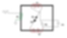
If the signal from PLL output "G" doing directly to "G" cell driver , then in the gate time TIP120 is turn-on and primary is also turn-on.
Please consider how the VIC behave in that case --- maybe half core of primary and L2 is saturated or became like electro-magnet in the gate time? How this influence the secondary and L1 and water cap interaction in the gate time?
In the gate time when primary is turn-on , this cause that the core of primary became like magnet, The current that flow thru water gap enter to L2 choke and generate magnetic field that is interacting with magnetic field of the core ( primary is turn-on ) - this cause the choke of current flow - restriction current.
=================
Right now I'm putting 3V square waves to the primary coil.
The rise time of the pulses going to the TIP120 base is 330ns and the fall time is 1.2us
I have my drive circuit setup on a breadboard.
It produces variable amplitude pulsing during the gate "off" time and also gives me an adjustable DC bias if I need it but right now I have the square waves going to 0V.
Even when I add a 500mV bias still no resonance?
I have been using the frequency sweep on my signal generator. It sweeps 1Hz per second with a resolution of .01 seconds.
Cell is 175pF and L1 choke is 1.221H, calculated resonance is 10,870Hz.
Calculated is different from real world. The range for resonance is up to 25kHz. With frequency doubled, it takes you up to 50kHz.
I am scanning from 10.7khz to 10.9kHz in a period of 5 minutes....
Sweep up to 25kHz and see which frequency has a higher peak to peak RMS voltage.
Find your frequency doubled. That's one step for a confirmation.
================================================
I have discovered the problem! I think!
I decided it would be best to isolate the circuit from the cell then the coils individually.
================================================
I applied a 390pF capacitance in place of the cell and still could not hit resonance.....
So I then removed the L1 choke from the circuit and placed the 390pF cap in series with the L1 choke and a resistor.
I hit resonance with the coil and cap in series but the voltage magnification only grew to 6X the applied voltage.
I did the math and determined my voltage was only 1/100th of what it was supposed to be at resonance.
I then tested my freq gen to be sure it could supply the current at resonance to be sure it wasn't the culprit. It produces more than enough current.
Not only was the voltage and current low at resonance but the resonant frequency was about 1.3kHz below what it was supposed to be.
So, what can effect resonance so much that it reduces the coils q factor?
I believe it is the aluminum box
I have my coils mounted in.
See, the coils not only have a distributed capacitance between the windings,
there is also a capacitance between the coil and the case.
Since the coils are nearly identical to Stan's in the number of turns and wire size
I don't think it is the Cd that is causing the problem..
.It's the C between the coils and the case.
Unfortunately this is going to create a lot of work to fix.
My coils are mounted very well in that box, so perhaps a sturdy plastic box is needed.
==============================
Depending upon the magnetic configuration, a metal case around such a transformer can act just like a shorted turn.
I've seen a lot of people try to mount a power toroid transformer with a bolt through the middle connected top-n-bottom to a metal case. It no worky that way.
I'm glad you may have found the problem, but it also looks like you got way ahead of yourself building a fancy enclosure before things were ready for prime time.
A small piece at a time, making sure everything is working as it is suppose to before moving on to the next step is the best approach.
And don't assume anything. Make absolutely certain.
====================
So the AL box lowers the resonant frequency by adding more capatance. Thats not a bad thing??? I don't think?
Thanks for posting your findings.
Also, with any kind of resonant system, you should be able to apply the ping test.
Basically hit the circuit with the fastest, sharpest pulse you possibly can and watch for any ringing on the scope after the pulse.
Use your cursors on the scope and find the exact cycle time; this should give you the resonant fundamental frequency you can tune to. From there you can find all the harmonics for quarter wave resonance and set your signal generator to match any particular one you want.
=======================
I just went and simulated the circuit and I think it could work....Just need to reduce the frequency and search around more.
The bandwidth of the circuit is so narrow that it makes it very hard to find....especially when your 1kHz past where you think you need to be.
I'll do more testing tomorrow morning at lower frequencies.
The alum case will increase the capacitance of the coils, it's just like putting a alum dome on top of a Tesla coil. It all has to be factored in.
As I told brad if you lay your coils on a wood table and move them to a plastic table or any other material once you get them to work, It is enough to change things and stop it from working.
So what every you put your coils on or in, expect it to change the capacitance of the coils. Its best to use a alum enclosure like Stan did on all of his VIC and factor the capacitance in.
Well, It looks like I still have more problems to solve. I think the differences in choke capacitances Cd and the capacitance to the case (I'll call it Cc) are making finding resonance difficult if not impossible.
This morning I used the sweep function on my signal generator to sweep from 8kHz to 10kHz over a period of about 33 minutes (1Hz/sec).
No resonance found. The work continues.
Here you can see the signals...The yellow shows the primary coil current via a current probe I made. The blue is the signal to the base of the TIP!20.

I also need to say that calculating resonance between the L1 choke and the cell gives me a frequency of 10,735Hz.
I measured the L1 capacitances and simulated the equivalent circuit, then found resonance had dropped to 8640Hz.
What is the blank time in between bursts?
If that's gating, you have it backwards. Gating is energized not relaxed. And you shouldn't need very much gating--just enough to set the core magnetization bias--goes back to what Russ and I were talking about with flux walking. I would gate for maybe three pulse widths, then pulse normally for the next 97 pulses in a 100 pulse cycle, just for starters.
Are you testing with your cells dry?
Also, I'm really thinking you need a few wraps of wire for a pickup coil. You need to see magnetic ringing which could be obscured from your primary injection signal. I have no idea what kind of amplitudes will show up as you get close to the resonance point.
I'm not in any way a master of this technology, so try my suggestions as you see fit.
If you want to, please try a ping test with some sort of pickup coil/wraps. I'd be very curious myself if you detect any sort of ringing and if this ringing can be analyzed to find the actual resonant frequency.
=======================
You reminded me that my gate frequency was incorrect. I calculated it using the L/R time constant of the primary coil like Ronnie explained earlierbit I calculated it incorrectly.
Also, are we sure gating is energized?
Ronnie's waveforms from before looked like they weren't, that could be my mistake though.
Another thing I'm not clear on is if I need to add a dc bias and if so how much. I've tried adding the bias before and still no resonance.
I'll try to figure out a way to make a pickup coil and do the ping test you mentioned, hopefully tomorrow morning. Thanks for the idea.
Update:I've been reading on the ring down test. If you count the number of cycles till the voltage goes to zero and multiply it by 4.53 you get the circuits q factor.
So I should see about 70 pulses.
===========================
Also, are we sure gating is energized?
Ronnie's waveforms from before looked like they weren't, that could be my mistake though.
The patent and estate photos say the gating is inverted from what we all thought. Ronnie confirmed that to me as well.
I'm not sure where he had his scope probes connected. If they were in front of the driver, the driver definitely inverts the signal. If he had the probes between the output of the TIP120 and ground, that signal is inverted from what the primary sees.
If you look at the PLL, pin-5 (INHIBIT) must be held low for the PLL to run. When you bring pin-5 high, the PLL stops at a low state; that same signal goes to the driver which holds the primary energized. Pin-5 is where the gating signal goes.
========================
Another thing I'm not clear on is if I need to add a dc bias and if so how much. I've tried adding the bias before and still no resonance.?
No DC bias to the primary. Not on Stan's circuit. The bias you are after is purely magnetic and that comes from the gating.
DC bias on the cell, that's another story. That's your polarization from leakage current and the charge factor being unbalanced and out of phase. I'm not that far yet, so I can only relate what I think needs to happen.
=====================
I'll try to figure out a way to make a pickup coil and do the ping test you mentioned, hopefully tomorrow morning. Thanks for the idea.
My thought was to use a current sense transformer. A higher frequency one like the ICE CT07. Take maybe ten turns of small wire around your core, go through the current sensor all ten times, then terminate the two wire ends with a 10 ohm resistor.
You should see some sort of signal on the current sense transformer when you pulse. Don't let the voltage on the current sense transformer get too high or is will smoke the windings inside. Use a shunt to keep it in range.
You may also want to move the ten turns of wire around to different places on the core to where you see the best signal or preferably the best ringing.
========================
Update:I've been reading on the 'ring' test and came across something interesting...One person on another forum said if it takes 10 cycles for the voltage to drop to 1/e then your Q factor is 10....If that's true I should see about 350 oscillations?
Q indicates the damping factor--the higher the Q, the longer the oscillation runs before it damps out. In reality, it never damps to zero. It just gets really too small to measure.
The ping test is an electrical means to ring a bell and listen. If you have any resonance at all, your cell, coils and core will ring at some natural frequency.
From what I understand from Ronnie, the higher the voltage, the higher the Q, which is why you need to start your tuning at low voltage so you can find resonance while the Q is rather flat.
As you increase your voltage, the Q goes up, gets sharper and it gets tougher and tougher to zero in on the exact frequency.
This is why Ronnie has stated several times, never, ever make frequency adjustments when running at full power.
The Q is way too sharp and just a few Hertz will knock it out of tune, then things smoke.
With that in mind, you can see why Stan's circuits have a PLL to constantly listen to the ringing and maintain phase alignment.
A PLL is the only thing fast and precise enough to make the needed adjustments when running flat out.
Current signals of a VIC
Special Thanks to BRAD and Matt for FINE WORK getting the following into the Public
So, I used my current pickup coil placed on the lead between the secondary coil and L1 choke. I found peaks at 28kHz and 14kHz.
I tried pulses, bursts, and square waves at varying frequencies and continued to see the 28 and 14kHz peaks...What's cool is when you zoom in you see frequencies over 11MHz....and I'm sure they go into the GHz range from my own research a while back.
I also tried placing my probe directly on the insulated wire to be sure my current pickup coil was not effecting the peaks, it wasn't.
Here's a few shots.


Cool stuff
Your scope appears to be a lot like mine.
Try a FFT run and see if that shows the peak frequencies. Not nearly as good as a true spectrum analyzer, but you appear to be getting good signal so it should still show us what we need to know.
Something else worth investigating--biasing the core. Here's my thought...
Forward magnetize the core with 12 volts, just for a second, then ping ASAP as you did. Next, reverse magnetize the core and try pinging it again.
I'm very curious if the response changes at all.
If it does, then we are getting pretty certain as to what high-state gating is actually doing.
Thanks for the feedback,
I'll try the FFT tomorrow morning.
kudos to you for being the first within 6 years to show current signals of a vic.
now everyone should start thinking about the question why there
is high frequency ripple in between low frequency pulsing ...
From what I can see there are a lot of harmonics in my VIC circuit, They go beyond frequencies my scope can pickup. The source of those HF ripples during the gating time is a question I wish I could answer. What do you think?

I tried doing an FFT today and I'm getting mixed results...
I am seeing some peaks at 8.3kHz but they change often.
The FFT has me worried as it's not showing any clear signs of a center frequency..
.it looks like a lot of harmonics at similar amplitudes...
I have to admit FFT is new to me so I don't feel like I know what I'm doing here.
What kind of signals and frequencies should I be putting into the primary coil?
======================
maybe it´s antenna voltage/current with transformer coils working as LC-filters damping some airborne frequencies while others stay uninfluenced constant.
switch off pulsing and observe if signal stays constant or amplitude gets lower over time.
=====================
Some of it drops when the circuit is turned off....Some of it is noise getting picked up liked you mentioned because it doesn't go away even when the probe is disconnected.
The amplitudes are extremely small.
=====================
Well even with a semi pro winder three things just are not Easy to get exact.
But thats ok. It still turned out well.
One half done. I have about 5 sets of theses coils with different wire on them. So this wire i have here seems like it will handle the HV stress well.
I also took extra steps to place some ptfe linners that go in the bobbin edges.
I added extra windings so I could take some off.
3200 turnson the sec
650 turns on the pri.
It's about 80ohms for the 3200
and 11.3ohms on the pri.
More measurements later.
I do not know how I had all the patience to wind all the coils I have laying around.


I can hear Stan saying,
"The only way this technology will come out is if the good people of the world make it happen."
I'm still trying to figure out what's going on with my circuit...There is no clear sign of resonance that I can see. The problem is, I wonder, if the circuit has to be in full operation in order for resonance to appear?
This morning I connected a 390pF cap to my VIC to see if it was the cell that was causing my issues or the coils (I'm thinking it's the coils).
I performed the ring test again and see the same, harmonics and a possible resonant freq but it's hard to tell. Even on my FFT there are no clearly defined peaks, the peaks change continuously. I think we are starting to see what it is that makes this device so hard to replicate.
Anyways, my next test will be to remove the coils from their AL box and try the ring and FFT tests in the open....I might be able to get to that later today.
Here's a quick shot of the ring test I performed with a 390pF cap in place of the 180pF WFC.

that's quite interesting brad.
I had know prob finding resonance. When I was doing this 2 years ago.
I'm getting closer. Will be able to help you.
Even with the 2 core I was able to find resonance. What max voltage peek have you seen?
This one is not bad at all. Tuning it all in. Resistance is really close to the same.
But slightly off due to the other coil not wraping that well.
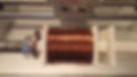
Well, I finally found resonance, too bad it was with a 390pF cap and not the WFC.
It's easy to see on the FFT when using a regular capacitor in place of the WFC. Of course after I did this test I tried the WFC again and couldn't find resonance anywhere.
I know for sure that you can't use the Bandwidth formula for the VIC, If so I would have hit resonance a long time ago. Here's a pic of what resonance is supposed to look like on an FFT.
I haven't seen anything close to resonance yet. I know I'm close but somewhere I am missing something or have a problem to correct.
Who knows when I will actually see it work? Hopefully soon

do have the asymmetry in the L1 L2 ?
Meaning the L2 has fewer turns?
If so, how much of a difference in turns?
If you want to, there are quite a few liquids you might consider pouring into your cell to see if the capacitance becomes anywhere near the 390pF capacitor you are testing with.
http://www.engineeringtoolbox.com/liquid-dielectric-constants-d_1263.html
Are you certain your cell doesn't have a loose connection or possibly a short?
There's got to be a good reason why a real capacitor works and your cell does not.
Dielectric Constants of Liquids
Some fluids and their dielectric constants or permittivities
The Dielectric Constant, or permittivity - ε - is a dimensionless constant that indicates how easy a material can be polarized by imposition of an electric field on an insulating material.
The constant is
-
the ratio between the actual material ability to carry an alternating current to the ability of vacuum to carry the current
The dielectric constant can be expressed as
ε = εs / ε0 (1)
where
ε = the dielectric constant
εs = the static permittivity of the material
ε0 = vacuum permittivity
The Dielectric Constant of common fluids are indicated in the table below. The Dielectric Constant is in general influenced by
-
temperature
-
moisture levels
-
electrical frequency
-
part thickness

Oh man. Well that one is really good and L1 and L2 are all most identical.
Sec is ever so slightly different.
So I may re wrap the sec.
But good thing is that I think no got the coil winder tuned in.
At least for this bobbin and wire.
Funny to think I printed these bobbins over 3 years ago.
Taking mesurments again.
Seems impedance with no core and 100Hz is spot on 100 ohms.
Careful, when taking the end pieces off with the core in. That's how mine broke in Colorado. I'll need to adjust the inside clearance for them.


I measured my coils again tonight and realized the secondary coils inductance is about 300mH (20%) too high. I knew that before but at the time I didn't think the secondary coil inductance would be a problem...the more I study Stan's tech the more I realize he did everything for a reason.
I checked my cell connections tonight and they are all good. I am getting the signals to the cell.
===========================
very delicate hands here.. always have clearance here.
i use the Steel ones i have first to get the fit right... thanks for the heads up tho.
Brad, you still have one good core right?
here are the measurements on air core.
i did not see the need for C measurements,
( i don't like the way that meter reads them any how)
This is fresh off the winder no adjustments yet.
Ronnie, what should i adjust from here using your understanding of tuning. ?
( with theses measurements and no core)
everything is over the 3000,3000,3000,600
because from my last coils the resistance was to low,
so i have plenty extra to match stuff by removing turns.
ill play dumb, teach me good sir.


the only way I could find resonance with the 390pF cap was when I removed the diode.
Resonance occurred between the secondary coil and cap....So today I'll be adjusting my secondary coil inductance.
When you hit resonance before did you have the diode installed? Was your vic similar to Stan's measured values?
Btw everyone, what do you recommend and what are you using for an LCR meter?
I have a small one I bought on eBay a few years ago that works ok but doesn't have a case. I also have a mastech that worked fine a while but hasn't given me good measurements lately. Both were from China so I don't think they're very accurate.
Between the two I was getting completely different readings. So I took my coils and measured them on a Sencore LC103 and got better readings that were different from my meters at home.
Now I'm wondering if I should invest in a better LCR meter?this is the one i have been using
https://www.globalmediapro.com/dp/A26CQ3/Tonghui-TH2821A-Portable-LCR-Meter/
honestly, its ok, but there might be better...
~Russ
also no LRC meter i ever found measures the cells right except that cheep one with no case ( prob the same one you have) Russ, do you have a fairly large inductor of known value in Henrys?
I would think you could connect such an inductor to your cell and do a ping test on the resonant circuit. The frequency you get can be used to calculate the missing capacitance value and should be pretty darn accurate. I'm not sure what voltage you would need to ping this with--keep going up until you see a definite ring I guess.
I just don't see how charging an air capacitor with a bench power supply to get a time constant can be accurate. I can't imagine a LCR meter doing it any better either.Matt i think thats a bad idea. i would use the time consent measurement and a scope.
like this theses measurements seem to be almost par on with that cheep LRC meter ( with no case) so its got to be doing something similar i think. Yeah I'm sure we're all using the same LC meter. At work we have a $3k LC analyzer. I'm very tempted to bring my cell in one day to see what it will show.
theses measurements seem to be almost par on with that cheep LRC meter ( with no case) so its got to be doing something similar i think.
yeah your not going to hurt the meter, do it! oh also i have been insing this LC network analyzer from NI. its a kit from mouser, web mug was using it way back when, it dose a nice job.
i haven't used it on the cell.
ill get the number when i go home, i cant remember the part number.
===========================
I made the adjustments to my VIC tonight. Inductances are a nearly perfect match!
The problem I might come across next are the resistances.
Mine are all a little low. Primary coil is 9.9 ohms.
I wound extra wire on all bobbins then removed it, but my meter was not reading correctly.
I also played around with different frequencies looking for resonance.
I think a good way might be to use a current sense transformer/ current probe.
I made mine, it works great and it isolates the oscilloscope from the high voltage.
At resonance we should see peak current.
I found a few peaks. I'll post shots of them tomorrow or Thursday. Also, now that I changed the secondary coil inductance the FFT is working.

Ronnie, are you using the same MUR1550 diode in the VIC that Stan used?Right now I'm using a MUR1100E.Yes, I found 2 of them several years back on ebay and snatched them up.
I found an alternate to the MUR1550, it's the NTE6248. I might buy a few of them if I can't find the others.
I have been using MUR1560. Its the 600v equivalent. You can find these new.
So, looking at the NTE6248 datasheet I noticed it has a rather high capacitance when reverse biased(145pF).
I looked at several MUR1550 datasheets but none of them list the capacitance.
This might be an important thing to consider. I'm going to search until I find a MUR1550 and just go with it.
Like I mentioned before, the more I work on the wfc the more I think that everything Stan did had a reason.GPS said he found 2 MUR1550 diodes years ago..
But we know he has made many VIC's?
This suggest that he is no longer using the MUR1550....
I am using a 1N1198 ....Big and red.
This must have a large PF number but the PDF does note state the PF?I've used both types, must be fast switching and voltage rating 500 volts and above they all will work.Thanks for clearing that up Ronnie!
agreed, a good video.
So we take a square wave that has an infinite number of odd harmonics (one of which is very useful for the deconstruction of the water molecule) and apply them to WFC.
If the impedance has been set correctly, all but that one harmonic is absorbed in the impedance match. The one of particular interest continues to bounce/reflect ad infinitum because the water and circuit will not absorb it. This particular harmonic continues to grow and accumulate upon the back of previous waves injected.
So what frequency, what harmonic is this wave? Could be 22Ghz for all we know.
It's well outside of our measuring instruments, but it's crucial for splitting the water molecule. We know it's there because it was sourced from a square wave and we know it must be an odd harmonic.
Beyond that, all we need to do is keep it alive and allow this frequency to add upon itself cycle after cycle.
At some point the amplitude will become so strong in comparison to its neighboring harmonics, it dominates the process, though we might not even be able to measure it
. We will know it is there when we see the gas production in the cell because
no other wave could be responsible for that phenomena.
after making a few adjustments to my VIC I'm getting some pretty waveforms!
Blue trace=Signal at TIP120 Base
Yellow trace=Primary coil current
Still not seeing resonance yet, but I also haven't scanned any frequencies since changing the coils.


Hey, it's the sperm wave
Let it rip
I wish it would have been true resonance. It's ok though, it will bring me closer to the finish line and teach me along the way.
Everyone,
I spent about 6 hours yesterday testing and troubleshooting my VIC.
First I got the 28kHz waveforms I showed earlier, everything looked right except the voltages were very low in amplitude.
So I set out to find where the low amplitude resonance's were coming from. I figured it was the chokes SRF and that turned out to be right.
In my troubleshooting to find exactly what resonance was occurring I tried isolating the circuit in several ways.
-First I disconnected my cell and put in it's place a much larger capacitance, 390pF.
a. Result-Still seeing resonance in the 22-28kHz range....
-Then I removed the capacitor and left the coils open
b. Result-Still seeing resonance in the 22-28kHz range
-Next I removed the VIC from it's aluminum box
c. Result-Still seeing resonance in the 22-28kHz range
So now I knew that the box was not causing the coils to resonate at it's srf-it was only increasing the srf
-Next I adjusted the choke inductance values and tested again
d. Result-Still seeing peaks in the 22-24kHz range
-Next I added a DC bias to my signal
e. Result-no changes, still seeing resonance in the 22-24kHz range
-Next I tried placing my current probe at different areas in the circuit to be sure it was not effecting anything
f. Result-Current probe has no impact on resonances
-Next I disconnected each coil and tested it on the FFT to find it's SRF
g. Result, L1 choke SRF is 25kHz, L2 SRF is 24kHz
So now I knew for sure that the resonance I am seeing is the chokes SRF
What is cool is the little LC meters many of us have will measure the choke capacitance
by placing a lead at each of the coil.
I tried this and came up with capacitances for each coil in the 30-35pF range, take the chokes inductance and calculate the SRF and you get the same frequencies 22-28kHz.
So, I went ahead and looked at the coils damping factor, thinking that may be the problem.
The coils are underdamped but only a few ohms different than Stan's.
In order to critically damp them it would require a much larger resistance to be added.
So it seems like the coils SRF should not be the problem here?
RONNIE,
Have you seen a similar low amplitude resonance in your circuit at around 20-30kHz?
Have you tried measuring the capacitance of your coils, and if so did you get similar results (30-35pF)?
Not sure what to do next....Start over and build a new VIC or keep working with this one.
Some fine work brad.
Thank you for the deep details.
I'm really set up already to start testing stuff.
So if there is anything you want me to test on my flat core Vic let me know
I'll be going over all my notes and trying some stuff today. Will see where we get.
==============================================
==============================================
one thing,
Can you measure the capacitance of your coils and post them?
Just curious to see if you'll get the same values.
I still think my coils should work, but tuning into resonance is more complex
than just turning a knob.
I scanned 5-10kHz in 10Hz increments and saw no sign of resonance anywhere, yesterday?
If you think of the cell as a efficient capacitor then you can calculate the Q
and bandwidth of the circuit,
then finding resonance should be easy,
if I remember right my VIC had a calculated bandwidth of 74Hz.
I think the water has to change in some way before resonance will show up,
and that's the hard part?
So, in essence you could have the circuit at resonance and nothing will
happen until the water does whatever it does before resonance appears.
I think I've probably hit and passed resonance multiple times but didn't notice
because I didn't keep it on the frequency long enough?
There's got to be something more because finding resonance in a typical RLC circuit is easy.
Brad. All my old coils including the ones your using are posted.
Not sure how everyone keep missing that. Lol.
But! It would be really good to add your coils in that spred sheet. And re post it.
There is a tab just for that.
http://open-source-energy.org/rwg42985/russ/RWG%20Readings%20and%20Extras%20-%20OSE%20Forms%20-%20Gries%20Petty%20Research%20Updated%2010-25-14.xls
All my old coils have C values.
The ones I just did I did not measure. Because I don't trust the measurements.
So take all the C values with a grain of salt.Little at a time.
Now I can take turns off better.
Need better shims tho. Lol will make some soon.
Just used what in had for today.
I can add my values but I'm still making adjustments. My secondary and choke coils are about 3 ohms below but my inductances are the same as Stan's.Ok. Well one things :-) for sure. Even if you get them matched exactly in all areas. I bet there's still more to know.
Aka their is more about the tuning than matching stans coils. Due to the things that need to be understood. All the small things I think Ronnie understands. So the hope is he / we can teach us.
I have a hunch the coils and cell are critically important, but the magic could be in the electronics.
If a few of us can get things working on our bench, then we'll be in a position to find out.
I've been replaying in my head a lot of what Ronnie has said already and I'm starting to feel the answers are soon to be discovered.If Stan's tech was easy more people would have had it working by now.
I spent several hours testing and troubleshooting the VIC once again tonight.
I figured out that you can pickup the signal with your scope probe about 1/2 inch to 1 inch from the chokes..
Tonight I adjusted my choke values once again. I also tried swapping the L2 chokes direction.
I saw frequency doubling tonight but no resonance...
I also saw the choke coil resonance around 20-24kHz.
I'm starting to wonder, if I hit resonance while scanning would my power supply switch current fast enough to see resonance?
Just trying to think of everything that could be going wrong.
I've been scanning frequencies again after adjusting my chokes several times.
I just figured out my function generator has amazing resolution on it's sweep function..
..It can sweep 1Hz in a maximum time of just over 8 minutes at a resolution of 1uHz. If this can't find resonance, nothing will!

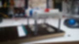


If you lower the voltage,
that will flatten the Q and any resonance that might be there will be lower
amplitude but over a much wider bandwidth.
If I'm understanding Ronnie correctly, that's the major reason why you
start out at lower voltage--it's not tunable otherwise.
I think your right.
In all my testing the primary coil only sees 2.5V.
I've had a lot of free time this weekend so I'm trying to get as much testing in as I can.
Watching the FFT as I scan frequencies...
I wonder if electrostatic fields effect the cell? I have everything on a plastic table in a carpeted room:-/ I just bought an ESD mat and grounding kit.
Might help, if not I needed it anyways!Oh man. Anything that can act as a capacitor will really mess you up.
This system is so hary that even your hand getting close to the cell will mess it up.
Just think aboit all the things that are close and you move around.
I have seen systems that you can tune with your body capatance. This is no diffrent!!!
The circuit is not an antenna. The circuit should be stable and isolated from outside influence.
Russ, That is one reason why I had my coils in an AL enclosure.
If you look at Stan's Cell you will see he has a thin aluminum strip covering all the connections, that's to shield the connections and cells from outside influences. I am starting to think any nearby power source, radio, computer, light etc will influence it and possibly prevent resonance.
I have a 6 cell unit and the connections are out in the open....I've been trying to figure out a way to make a cover/shield for them.
I've had my function generator going for a few hours now on the sweep function. It's been sweeping 1Hz every 10 seconds at a resolution of .000001Hz...So far I've gone from 8.000kHz to 9.1kHz...Nothin yet Didn't GPS say he was using 10-20 HZ?I scanned for resonance 5 hours today. I went through 8 - 9.8kHz sweep on my function generator over that time.
Did I find resonance? Nope!
While scanning I decided to collect some snow (Ronnie's suggestion) and let it melt to use that water in my cell.
The interesting thing is the snow water increased the capacitance by a big difference.
Typically with distilled water the cell reads in the 165-185pF range.
With the water from the melted snow it's showing 520pF. It might be that the water is more conductive so it's throwing the meter off. That's my guess.
I also sent a quote request to have a shield made for my cell. I'm looking at having it 3D printed.
Not sure what to try next as far as resonance goes?
===================================
I also sent a quote request to have a shield made for my cell. I'm looking at having it 3D printed.
Not sure what to try next as far as resonance goes?
what material were you thinking about 3d printing in?
yeah, you know there is got to be things we are not aware of.
I mean i know there is,
i have worked on Many industrial systems over the times and the ones that you have to " tune" ( Ex. weight systems ) you have to go step by step and go through the owners manual a few times before you can get it right. and only after that can you do it on your own with out the book. with some practice...
its quite unfortunate but this is the way this system is. currently as far as I'm concerned Ronnie is our only book. we need him to keep pushing us in the right direction.
i spend some time last weekend tuning some stuff and i remember so much i did in the past. things felt so close, looked so good on the scope. but... just not there.
with that said. lets keep chugging along and Ronnie i encourage you to keep posting when you can. i do feel we all gained alot more understanding of what the system is doing over the last 4 months., However we need to do the same thing about Tuning.
so Ronnie, can you post more about tuning. i know you understand it in your head, each step you need to go through to get to the next step.
theirs a big change that starting out with looking for resonance is the wrong way to do it.
so if there's a chance to getting this working. I feel its going to be through Ronnie teaching us the tuning steps.
any thing you can guide us with Ronnie that would be good. we are not looking for the answer, we are looking to be taught the steps to our own rediscovery.
i spend some time last weekend tuning some stuff and i remember so much i did in the past. things felt so close, looked so good on the scope. but... just not there.
The "so close": What to look for ... Highest voltage output at a resonant point. Low current is stable while high voltage is unstable, and voltage-to-current phase offset by 90 degrees. PLL locked on a phase angle.
, I was just going to have it printed in abs.
Any chance you could print me two half cylinders, which together will have an i.d. of 5.01", an o.d. of 5.25", and a length of 3"?
I'll be happy to pay for it and shipping. Let me know if your interested
Haxar, that's what we would all like to know. What signs show up to let you know your close to resonance. I can tell you is not like any other resonant circuit. I can watch the FFT, the primary coil current, secondary circuit current and see the same peaks over and over at various frequencies.
It's difficult because at many frequencies the same waveforms at similar amplitudes are produced.Resonant points are peaks in amplitude. There could be many resonant points to lock onto. I think there is an assumption floating around that there is just _one_ resonant point, when there can be many, with the same amplitudes. Stan did not mention "the only frequency", other than the 50kHz mentioned in a tape of his.
here's a drawing of what I need x2, as you can see it's just a short pipe cut in half


Can you measure the capacitance of your coils and post them? Just curious to see if you'll get the same values.
I still think my coils should work, but tuning into resonance is more complex than just turning a knob.
I scanned 5-10kHz in 10Hz increments and saw no sign of resonance anywhere, yesterday?
I tried this once with a impedance measuring device…
You can only "know" the distributed self-capacitance and inductance of the (VIC) coils if you are using an impedance analyzer by calculating them from measuring VI (voltage, current) parameters:
Frequency, Real, Imaginary , Impedance or Magnitude (SER or PAR). Just connecting an RLC meter won’t do it right, because it only using some fixed frequencies 100Hz, 120Hz, 1kHz, 10kHz or 100kHz etc.
You need to find the peak (SRF).
Then connecting the coils in series (opposing mode) will drop the inductance due the Mutual inductance. What you think will happen with the distributed self-capacitance? It changed too, right?
So using a impedance meter with frequency sweep you can test the (VIC) DUT (device under test).
You need to look for a first peak (SRF) where the voltage will be the highest on both chokes equal but opposite voltage outputs (B+ and B-) and here is the SRF frequency.
Then also changing voltage amplitude to drive the circuit changes the inductance of the coils (core material) and you end up with different values but I think it is a scaling factor of the SRF. Not sure…
What k parameter do you guys use for calculating the mutual inductance?
===================================
I have been deeply thinking about SRF, & How it can be directly applied to the known "what to do's"
so the first thing i want to do is that, measure all the SRF and resistances and try to determine if there is something useful there.
Ronnie, do you have anything to say about this path?
Webmug, using the same device you used i will be checking for SRF. would you mined posting any information on your experience even more than you already did?
i think it would be helpful. also i dont have the device name here with me and forgot to post it. if you can that be great, if not ill get mine when i get home.
Brad, what have you been thinking as of the SRF and tuning / math? can you go deeper in to your thought process?
thanks!! hope to get some more data soon on SRF of the coils i made.
======================
Using that EVAL-AD5933EBZ Rev. C pcb, has some issues that I never solved. You need to use a calculated Rfb (feedback resistor) on the input opamp stage for a impedance you want to measure. So that Min,Max, impedance is the range of your DUT. The calculations are in the datasheet. So some Rfb switching is needed for the DUT you want to test. Then you need to calculate the parameters, C, L etc. from the Re and Img etc.
http://www.farnell.com/product360s/images/EVAL-AD5933EBZ/EVAL-AD5933EBZ-big-01.jpg
http://www.analog.com/media/en/technical-documentation/evaluation-documentation/537700023EVAL_AD5933EB.pdf
http://www.analog.com/media/en/technical-documentation/application-notes/AN-1252.pdf
For some arduino hacking use:
http://store.digilentinc.com/pmod-ia-impedance-analyzer/
Boy, some good stuff there Webmug.
Here's one little snippet to think about.

Webmug Self-resonant frequency can be measured with impedance analyzer that is the best and accurate approach,
but it can be done by "pinging" the coil with a short pulse with a diode and freq.
generator and watch the "ring" on the scope of its self-resonant frequency
across the inductor.
This is not the most accurate approach but can show the approximate value, since the real inductor has the characteristics of an RLC circuit.
WATER IN CELL?
Webmug you are correct.
You can't get accurate measurements using an RLC meter.
But I was not looking for exact measurements, just trying to rule out the source of resonance I was getting between 20-30kHz.
NO WATER IN CELL
I did that using 3 different methods.
1. The ring test
2. Test with signal gen, oscope, and a current pickup coil (current sense transformer) looking for peak currents.
3. Physical measurements
All three tests showed that what I was seeing was indeed the SRF of the choke coils.
This led me to find out that at one point I
accidentally swapped my chokes so that they were opposing each other.
As far as the SRF goes I don't think it has a role in how the VIC operates,
I think the coil capacitance plays an important role though.
There is another coil resonance that could be occurring which happens when the coils capacitance couples with a nearby object and forms a series resonant circuit.
Personally I think the VIC resonance occurs like Stan says,
between the L1 choke and the cell.
But it appears that more has to happen for the circuit to see the cell as a capacitor.
Like I mentioned before as you scan through the frequency range you see a multitude of peaks on the fft. Many of the peaks are about the same amplitude and no clearly defined resonant peaks appear.
There's got to be something occurring in the cell that causes it to become a real capacitance....otherwise all your doing is putting square waves into a non linear resistance, that's why you'll see a multitude of peaks but no clearly defined resonant point.
What your seeing are smaller oscillations of the square waves being broken up into an infinite number of sine waves (Fourier series ).....the resistances in the cell match to some of those frequencies and show up on the scope.
My scope only goes to 40MHz. The circuit operates in the audio range 1-20kHz, but when testing I have measured frequencies above 10MHz at very low amplitudes.
imagine if your oscope was creating loading effects,
preventing you from hitting resonance....
maybe you should look at the bubbles, and disconnect your scope
He should be running the cell dry at this point. If there is water in there, he'll have a whole other set of problems to deal with before there is any resonance.
I do tend to agree about connecting instrumentation to a device which actually prevents the device from operating correctly though. I've seen that happen many times before. I've also seen the reverse where the DUT only works when connected to scopes and such.
dont know why he would be running it dry... tap water creates a dead short.....
with just air its essentially just an open circuit with like no capacitive effects....
water should not present capacitive effects either, but alas Stan says it does
so we have no choice to believe him right?....
My scope is not directly connected to the circuit, it's coupled to a single wire going into the primary coil so the coupling is very small, at worst it would effect the vic much less than the pickup coil Stan used on his vic.
I am testing the cell with rain water in it, I tried distilled with no results.
Stan had test point to see the resonance on the output of pulser indicator circuit - test jack on the figure 9.
Voltage Doubling
Alright. After some days of printing new stand off holders for the Vic. I put the ferrite cores in the Vic. I use one thickness of clear scotch tape as a separator. I think these cores need a gap according to the high inductance values I get when there closed.
Cells are still dry.
Measuring the L1 and L2 coils with a reference ground as the straight connection between the L2 and Sec
Probes are 2.5pf and 40 Mohms so they must be factored in
I was able to get resonance between theses points at different frequencies.
Max voltages I was seeing was around 165vPk-Pk
What was interesting was that I was able to get a really nice
Doubling effect at a set F
But also get both coils resonating at a different F
Also, let's be clear here. Using STAN's circuit for driving at around 5v. Anything past around 10khz the pulse with across the primary is no where near 50%
in fact to get 50% duity across primary the coil at 20khz required 99% duity cycle input ( 1% Not inverted)
interesting.


Oh and something to add. I was only able to see the doubling on the L1 coil.
This makes sentence according to what I know about where the diode is placed.
It also makes sense because L1 is on the other core half away from the primary.
So let me ask, are you seeing any frequency doubling on the secondary?
Max voltages I was seeing was around 165vPk-Pk
You won't be jumping any sparks with that voltage but the frequency range of around 12kHz is encouraging.
I'll need to measure the sec.
Yeah. Nothing is tuned here eather. Lots of things to adjust.
I just wanted to see what happens "out of the box"
Ok. Quick before work day testing. Added the sec measurement.
So that's now blue.
You can kinda get the sec to double. But not really.
However. At low frequency's there is the quite large peek on the primary. Measuring across it. Its not ringing due to the diodes. But it is spiking. Allmoat 2x the input.
Here are a lot of photos for your viewing pleasure.
Remember gnd reference point is between the sec and L2
Yellow is L2
Purple is L1
Blue is Sec
Green is primary
I measured each ring with the cursers.
Ring test.


This is a rather interesting thing. You can see each coil ringing high or low.
But the L2 is always in the middle.


Here is trying to find doubling on the SEC
The voltages are so low it's kinda useless.
Also note that changing voltage really changes the behavior of this completely.
Also note that the sec is out of phase from L2 and L1


Yellow is L2
Purple is L1
Blue is Sec
Green is primary
More good hard data Russ. Awesome work!
Here's an annotated schematic for the ping test to study. Hope I have the data points correct.
Just looking at this from a distance with an untrained eye, it would appear you have the greatest number of windings on the L2, less on L1 and the fewest on the secondary.
I'm sure that's not the case, but I'm curious as to why the numbers come out like that. It has to be the inter winding capacitance responsible for the these ring points.
Each coil seems to be its own tank circuit.

I'll look into the duty cycle anomaly on my prototype and see if I can replicate what you see or not.
I see something quite clear in your testing that we are looking for frequency ratios. I don't know what they should be and how they change with voltage adjustments.
Mutual inductance of the coils is the other factor obviously. From your ping test I roughly get:
L2 -- 4x
L1 -- 5x
S -- 6x
I get the feeling we need to try several ping tests at different voltages and see if these change and if they try to converge on some common ratio.
how many loops does that single wire have?
i hope you realize that your scope now is its own RLC circuit....
and your VIC resonance will not coincide with your scope resonance.... your scope has capacitance and inductance..... its its own circuit now....
what i worry is that your scope "loop" is interfering with the VIC's space flux density distribution... how could it not??
====================================
Brad, just a question. if you use any plastic that like to be static charged, and you add some AL foil to it, are you not just making it wore?
i was able to show how much the human interference messes with capacitance. its not extreme enough that if you have things spreed out from where your working, you should be ok... ??
The shielding is not just for stabilizing the capacitance, it's to prevent energy from getting out and making you sick by overexposure to emr.
==================================
I'll look into the duty cycle anomaly on my prototype and see if I can replicate what you see or not.
Yeap. Confirmed. Get's worse as the frequency goes up.
I don't have differential inputs so I had to do each one separately.
First one is straight from the VCO output; second shot is between the TIP120 output and ground.
Again, because I don't have differential scope probes I always have to connect ground to power negative, so I really can't scope directly across the primary.
The signal to the primary is actually inverted from the second scope shot--duty cycle
is increasing with frequency.
This behavior must be intentional .
It's the first real reason I can see for all those transistors in the driver circuit. I thought it was strictly to create delay and that's partially true--it's a delay that alters the duty cycle.
So best I can tell, Stan was interested in keeping a certain pulse duration regardless of frequency. I'll try to find out what that duration is.
Maybe it will tell us something important about how the VIC needs to be tuned.
Just checked and on my VIC driver the duty cycle seems to be on a curve that peaks at 100% spot on at 16kHz. So this is the max frequency the driver could ever output given a 50% duty cycle from the PLL's VCO output.
Which tells me there is no point in testing the VIC beyond 16kHz to the primary. Any frequency higher than that would be just solid on to the primary winding.
This is by-design; I'm sure of it.
So it's the duration of the off-time that is critical to operation of the VIC. The off-time and the repetition rate of that off-time must exactly match what the VIC is expecting.
Anything else and you're dead in the water.mine was the same. Some of my scope shots are odd because I Measuring across the secondary. So they seem inverted if I'm not careful.
===========================================
A few observations from my testing this morning:
With the 520pF wfc I hit resonance around 7.6kHz....
but the oscillations between pulses are around 23kHz (SRF of the choke coils).
When I put a 390pF cap in place of the cell I hit resonance at 8.3kHz....
the oscillations are the same 8.3kHz.
In real resonance the oscillations should be the same frequency as what we're putting in....so, something is not quite right in my cell or VIC.
I'll look into it further later today.
===================================
Just looking at this from a distance with an untrained eye,
it would appear you have the greatest number of windings on the L2,
less on L1 and the fewest on the secondary.
I'm sure that's not the case, but I'm curious as to why the
numbers come out like that. It has to be the inter winding capacitance
responsible for the these ring points.
well there are MANY factors for theses rings right?
so not just inner capacitance.
we have the interaction between coils to think about too.
core coupling
theses will effect the SRF
also note that the Sec is not wrapped as nicely as the L2/L1 in my set up
however,
for fun i could start trying to match everything to be resonant as in Brad's description.
==================================
I've adjusted my coils L values several times but don't see any major changes
in the way the circuit is operating.
I keep seeing oscillations 2-3x the frequency of resonance. We should be
seeing the same frequency at resonance that were putting into the circuit.
When I use a regular cap the oscillations are in phase and match in frequency....
but with the cell....
==================================
What are you using as a driver?
We are starting to see that Stan's driver circuit... well is doing a particular function...
so as we learn you will need to make sure you understand why it is and what its doing..
. so you can be on the same track... just an FIY...
Cool, I noticed Matt said the duty cycle increases as frequency increases right?
=============================
HINT TOWARDS LMD
I've adjusted my coils L values several times but don't see any major changes in the way the circuit is operating.
I keep seeing oscillations 2-3x the frequency of resonance. We should be seeing the same frequency at resonance that were putting into the circuit.
When I use a regular cap the oscillations are in phase and match in frequency....but with the cell....
you all have a fundamental error in understanding of resonance
classical type of resonance is only constant repetition of the LC process which in itself is nothing special
and it can reproduce by any person in this world with a modest knowledge of electronics
see what Tesla says
No, I did not use that method when I was transmitting energy. I used it only in the production of those freaks for which I have been called a magician. If I had used merely undamped waves, I would have been an ordinary electrician like everybody else.
=========================

Not sure I understand what your saying. We need to put the same frequency in the circuit that is its natural frequency.
We might see frequency doubling but my circuit has oscillations 3X the input freq....Only resonance I'm seeing is the chokes SRF at 22kHz. My circuit should hit resonance around 7.7kHz. It does hit a peak there but the 23kHz oscillations show up.
Russ, what are you seeing your primary current at when your running a 50% duty cycle at say 5kHz with no gating?
Ris, the questions become:
What is this other method?
How do we generate it?
And how do we recognize it when have successfully generated it?
agree with that.
======================
I wanted to go back to this "mode change" I was talking about a while back.
we know this change happens due to the changing in capacitance of the WFC.
When the cells are dry you can use your hand to change the capacitance of the system.
There was something very strange happening that didn't really make sense
until thinking about it now.
If you go back and watch the video I published when I was doing tests you see me reach my hand towards the cells I can knock everything out of resonance or into resonance.
This is very important because this is the function between getting the process started and resonance taking place after you change capacitance by creating some initial bubbles.
This also happens in other systems but not quite the same.
This one is designed specifically for the water.
No. It's never 50%
Please take the time to scan my video I posted here. You can see it change.
If I get time I will go through each 1khz and check the duty
Oh by the way. This "mode change" was NOT somthimg that was "slow" it was like a "snap" in and out of resonance. Normally when you use your hand to tune resonant circuts it's slow to change. This was not that
The thing is simple we can all choose the solution that suits us
or we can find the right answer
======================
I get what your saying...I have put more power through the circuit but got the same results....Next time I will increase it further.
It's like the circuit doesn't see the cell at all. I can disconnect the cell while the circuit is on and it barely changes the waveforms....all the energy is being stored and oscillating in the coils.
I'm looking at my coil phasing and going over everything again to see if I've made a mistake somewhere.
Matt & Russ,This is where it get interesting, if your wfc has the capacitance of your coils... srf....? :) Loading the VIC has little effect....just a resistance...my guess.
Great work on the driver circuit....it's interesting to see how the duty cycle changes with frequency.
I'm clearly thinking there needs to be resonance within resonance--one works the coils; the other works the cell. One is a harmonic of the other and that harmonic is probably so high we can't even measure it with the tools we have.
@Matt,
This should give you an idea on what kind of Impedance the current restricts....Stan wrote LC resonance (|Z|=R series, Z is at its minimum=R value, current maximum) but those coils ring on the self-capacitance and self-inductance (parallel where |Z| is at its maximum value) so current is minimum on both sides. Confused? :roll:. That's why those coils |Z| peaks are maximum in the graphs I once plotted.
I guess my point is we don't have a clear comprehension of impedance.
Here is an impedance device, a carbon resonator:
But what frequency does it resonate at?
I can't measure any frequency with such a device, but I know it has impedance. And since we can't seem to measure the frequency, we just call it a resistor. I'm guessing it resonates at the same frequency of a DC source, like a battery, again way too high to measure.
Now if I put a square wave signal through this device, I have a modulated signal. You say, "You're crazy man. What's the carrier frequency?" I can't answer that, because I can't measure it.
When I put straight DC into an electrolysis cell, I also have a carrier signal with possible sub-harmonics. One of those sub-harmonics is probably acting at the correct frequency to split the water molecules. Which one? With an infinite number of them, no wonder we lose so much power with electrolysis. But what if we filtered all the sub-harmonics from the DC carrier except for the one that does the job? Bet that wouldn't take much power. You think maybe that's what the VIC actually does? It's a big band-pass filter? It eliminates all the components of a DC carrier leaving only the frequency needed to agitate a water molecule into pieces?
Just a simple viewpoint change. Could we be looking at the VIC the wrong way?
We have concepts of capacitors, resistors, inductors, diodes, etc, None of those actually exist in the real world. They are theoretical concepts. Real components share characteristics of most all of those theoretical concepts. They are all resonators of some sort with real impedances having real frequencies.The only problem is the coils have a much lower capacitance (30-35pF) while the cell has 520pF.
Well your example is kinda extream, but it would have a srf or inductance or capacitance. Maybe in the range you cant measure, true.
For the VIC coils there is impedance on a frequency we can measure, were it will be inductive or capacitive...for inductor we want inductive etc. but it will have a SRF where the |z| peak will be. Our coils have both in a sufficient range to let it resonate. http://www.cliftonlaboratories.com/self-resonant_frequency_of_inductors.htm
ou wrote the SRF hasnt a role in how the vic operates, so ask youself, what is the impedance on the srf?
Those three methods do not specify how you found the self capacitance of coils...you have two unknown variables L and C at a srf, can you elaborate more?In my vic I can hit resonance around 20-25kHz...When I hit that resonance I can remove the cell and the circuit is not affected. If I put a direct short in place of the cell the result is the same.
So, in my VIC I continue to see peaks in the 20-25kHz region. This even after I have changed the inductance values of all the coils several times, removed them from their box, tested each coil individually etc.
IS ANYONE ELSE SEEING PEAKS BETWEEN 20-30kHz?Brad. Did you scan through the video I posted? Cool to see you got hv out of it.
So I'm not the only one seeing the the 20-30kHz peaks
It's the live recording. Its long but you can scan through it.
Mine as it is is happy around 23khz. If I remember right. This is with some tape in between the cores. I will play with this gap to see how we can change it. With no gap I should be able to resonate much lower. More inductance. ...
But u can see all the resonant F I see from the ping test. Each coil is different. ~Russ
I show how it "jumps" out of and in to resonance. About 48 min in
I find quite interesting. It also shows the duty cycle changing.
Do watch it and tell me if theses things you are Also seeing Or if it's way off.my circuit does that same thing where it pops into a resonant frequency of some kind.....
http://www.cliftonlaboratories.com/self-resonant_frequency_of_inductors.htm
That's some good deep stuff there Webmug.
I suggest people read it and think deeply about what it infers.
I'll give you a hint: capacity, which is a word Tesla used quite often.
This capacity can be either inductive or capacitive, plus or minus.
If you think about it hard enough, you will question why we have two
separate terms for the same thing:
Farad & Henry.
They are the same thing with just a slight twist:
-
A negative Farad will not allow DC to pass,
-
but a negative Henry will.
Now think about what DC is or must be?
=======================
Here's where things get tricky.
We need the VIC to have the same SRF as the WFC,
then by way of sympathetic vibration, the WFC will resonate in-phase with the VIC.
The WFC charges up, then we break resonance with a gate and bam, the WFC charge
implodes in on itself.
What we don't want is the VIC and WFC becoming a tank circuit where they need each other to function in resonance. Instead the VIC is a tank circuit by itself, as is the WFC.
We just want both of them to operate at the same frequency in-phase.
We pump the VIC up to its SRF and the VIC will do the same to the WFC since it's connected.
Daniel " Marx Generator" 20 years of study to = a few words
Peak effect coupled with the surface tension of the water
When you go back to surface air gap , the potential difference reappears in the thin layer of water that remains and it produces this effect.
insulating the tubes with dbd or air gap via their conditioning would precisely enable the voltage to be increased via a simple RLC circuit.
And if it is isolated it does not arc and does not break the resonance
the voltage which increases near surface layer SKIN EFFECT => ddp more important =>
suddenly you must tear off electrons on the electronic layers closer to the nucleus of atoms (H O).
While with a strong current and a weak ddp it is the electrons of the outer electronic layers which are torn off.200V to 1.34A Your water with surface tension wouldn't behave like a capacitor?
Based on my post (see above) getting the voltages balanced.
http://open-source-energy.org/?topic=2785.msg42127#msg42127
======================================
Chokes:
L4:=1218.8e-3; C4:=108e-12; R4:=76.7;
L6:=1093e-3; C6:=96.85e-12; R6:=70.1;
coefficients:
L4/L6;
C4/C6;
R4/R6;
coefficients:
1.115096066
1.115126484
1.094151213
======================================
~webmug

should one attempt to get theses values?
say, have you done this calculation on don's measurements?
thanks for posting!
edited: 01/30/2017
@russ,
The coils inductance/ capacitance Don has measured are not the values on SRF but on (100,120,1k,10kHz) but yes I used them for the model.
Don also wrote that he only measured one coilpack and he has seen the coilwinder Meyer used and he wrote that he expected the coils on the other coilpacks would not have the same exact values. So my conclusion is that there is a L,C,R ratio/factor/coefficient to match the coils for balanced voltages. It should work on higher turncount coils (for higher voltages, Stan mentions). Stan wrote about coil "voltage" coefficients also for the Re which makes the EPP possible. Meaning it works for different coils...
You say you have approx. 3000 wnd on each bobbin so you can tune the coils.
What is the WFC resistance at 20degC and what is the capacitance? Using the measurements from Don I calculated the max windings needed to get the winding ratio from the resistance. You already know the resistance of all the coils: 219.2 ohms and of your WFC at 20 degC. Which is (in my case) 208.8 ohms and 1.0574nF for a cell. So the VIC is designed to match a 10 cell series load. (208.8 ohms * 10=2088 ohms) + (VIC resistance of 219.2) =2307.2ohms. So your |Zs| series is 2307.2ohms and a 10 cells series WFC has 105.74pF.
Using this |Zs| 2307.2ohms and our primary |Zp| of (220//10.5)=10.02ohms and lets say Np=539wnd (30awg,10.5ohm) we get Ns=8166.18wnd (30awg) separated over three coils on the core. That's min. 2722.06wnd per coil!!!
Looking at the LTSpice sim, the secondary coil is opposing the chokes and both chokes are aiding. When the secondary is aiding the chokes I could not get the voltage peaks balanced of the chokes. Also the secondary sets your voltage amplitudes of the chokes.
GPS was telling the dielectric (resistance) was changing from high to low only when the EPP is started. When the resistance (load) is lowered to a min. of the coils |z| which is 219.2ohms+ Re. 78.54 ohms is never possible. (78.54 is constant on a fixed temperature).
Looking at it as a resistance it is possible that the WFC load of 2088ohm (water) is going to be less and the voltage is rising. (see for yourself in the TLSpice sim, changing the WFC Re). Curve will get smaller and higher in amplitude.
What is still don't understand is if the WFC capacitance will change when the WFC resistance is changing due EPP. Result is the frequency will shift and the voltage will change. If this is the case the chokes equal but opposite voltages get out of balance.
My feeling is that this does not happen and only a fraction of the WFC capacitance is changing due ambient temperature and the Re will be less (not much due water inflow/outflow) and the voltage should go up.
~webmug Thanks Webmug for taking the time to explain This further.
in the sim,
Looking at the LTSpice sim, the secondary coil is opposing the chokes and both chokes are aiding.
can you change the configuration so that Sec and C1 are adding and the C2 are apposing.
I'm would love for something interesting to come from that configuration...
please try it and see if there is any positive result.
also, how dose the diode play in the sim with both configurations?
Circuit Design Tools & Calculators
Analog Devices’ Design Tools simplify your design and product selection process through ease of use and by simulating results that are optimized and tested for accuracy.
Analog Devices Circuit Design tools are web based or downloadable but always free to use.
-
Reduce your testing time and get to the finished product faster
-
Overcome engineering challenges and simplify calculations
-
Use industry leading products to create the best design
-
Be confident in the results and your solution
TSpice IV download link
Download LTspice
Download our LTspice simulation software for the following operating systems:
Download for Windows 7, 8 and 10 Updated on Jul 30 2020 *
Download for Mac 10.9+ Updated on Jul 30 2020 *
Download for Windows XP (End of Support)
You can play with it and try the circuit (see attachment)
webmug-tuned-vic2017.asc - 3.03 kB, downloaded 1332 times.
perfect-tuned-vic2017.asc - 3.89 kB, downloaded 1578 times.

Drive Circuit notes
I use a dual channel signal gen to produce the high and low frequency pulsing.
The +10V supply rail first goes through a 10k resistor, the circuit then splits, one leg goes to the collector of a 2n2222 which base is driven by the high frequency signal.
The other leg off the 10k resistor goes through a pot then to the collector of another 2n2222 that is driven by the low frequency signal.
The pot controls the pulse amplitude during the "off time".
The center post of the pot drives the base of another 2n2222 which drives the base of the TIP120. I'll draw up a basic schematic
Thanks Brad..i always thought i had to use 2 separate frequencies to make the offset..but didnt know how...

This circuit has two pots, one for adjusting the primary coil voltage amplitude and another for adjusting the pulse voltage amplitude of the pulsing during the 'Gate' time.
There are four options for driving the primary coil.
1. Gate time high-Current flows through primary coil during gate time
2. Gate time low-No current flowing through primary coil during gate time
3. Variable pulse voltage amplitude during gate time (via P2)
4. Continuous pulse frequency
Both high (resonant) and low (gate) frequencies are provided by a FeelTech function generator which provides independent frequency, duty cycle, and sweep functions.
The drive circuit, function generator and VIC coil are all powered by a Ryobi 18V battery and a programmable power supply as seen in previous videos. Here you can get the Multisim and image file/schematic
I had an input signal that was 10V high unipolar pulses with a positive 10V gate just like the diagram shows. I used two 2N3906's, one 2N2222 and a TIP120.
Output across the coil was like a continuous pulse with small dips between pulses???
It all works on the VIC card. Adam made a video of it all working that I seen.
Did you build the voltage amplitude control too?
Did you use an inverted gated input signal to the cell driver as shown?
BradK-Hybrid VIC Driver-April 2020.ms14 - 211.53 kB, downloaded 6 times.
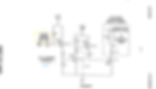
I don't have the voltage amplitude control circuit but have 2 adjustable power supplies.
I did put an inverted signal to the driver circuit.
I'll play around with it more this weekend.
Once again....Does anyone know the reason for the 2N3906'S and 2222.
I know the Q8 2N3906 drives the Tip120 base but what is the reason for the others?
Pretty sure those three transistors setup a fixed DC bias that keeps the TIP120 partially turned on at all times. This in turn keeps the primary slightly energized or should I say, provides leakage current.
Russ and I have been trying to figure out how this leakage current makes it way over to the secondary side, hence all the talk about flux walking.
That's what I don't quite understand. My simulation of the drive circuit in multisim does not give me a dc bias. I wonder if it's further back in the circuit or my sim is incorrect?
Looking at Ronnie's waveforms it's hard to tell if there is a bias there...Ronnie, on your scope shots where are you measuring the yellow trace? Is it across the primary coil?
If Stan wanted a dc bias he could have just added a resistor from a positive voltage source to the base of the tip120.
This is where I get confused because I've never seen anything in Stan's literature about a dc bias?Putting this out there because for some silly reason I never noticed it before.

Understanding Vee and Vcc
Vee is one of the pins from K3 card though DB9 to the VIC daughter board

this is where I get confused because I've never seen anything in Stan's literature about a dc bias?
Figure 4 (high-side) of the patent sure shows the gain and offset components going to the primary coil. Figure 5 (low-side) also connects to the primary coil on the opposite side.
So I think you need both circuits, best I can tell.
Doesn't look to me like either side of the primary coil actually connects to ground or positive power.
The high-side can be hard switched to the plus battery,
but I don't think you want it that way for testing--
there would be no way to start at a low voltage and work up if you did.
With two circuits like this on each side of the primary,
it makes sense why there is a 10 volt reference (VEE).
You only need less than two volts of DC bias at the most. Ronnie said about 1.23 volts is plenty.
==================
Brad, can you re post
" Looking at Ronnie's waveform it's hard to tell if there is a bias there...Ronnie, on your scope shots where are you measuring the yellow trace? Is it across the primary coil? "
also the Dc bias may not show up till after some cycles , so the sim need to be bale to "flux walk"
else you will see what you described in your last post i think.
"Output across the coil was like a continuous pulse with small dips between pulses???"
let me try to test mine when i get time this weekend., are you checking the Sig with a coil connected?
================
Brad, I may have made a mistake on the VEE voltage.
Try -5 or -10 volts for the VEE I'm thinking it was -5 volts.
Let me know if either works out so i can go back and change my post that I made.
VEE is normally referenced to the emitter of an NPN transistor (VSS--source for N-type MOSFET), so yeah, it should be near ground level. And since it is connected to the emitter of a PNP transistor, it must be higher voltage than the collector side which is at zero volts. I'm guessing more likely +5 volts--can't be below zero. Okay, I don't "think" it is below zero.

All this talk is good though:
I think I see now how Stan possibly avoided or controlled flux walking. He has essentially a bipolar configuration by driving the primary from both sides.
Being able to shift the voltage around is how you balance the volt-seconds.
IEEE Standard Letter Symbols for Quantities Used in Electrical Science and Electrical Engineering See page 26.
Back up here of symbol book
I'll get with Adam or Dom, they have the VIC card up and running. I'll get one of them on skype and see what the VEE voltage is for sure. Dom sent me a VIC card but I haven't got around to hooking it up yet.
When someone has the exact values for all the VDD, VCC, VEE, etc, please post that info.
I'll start working on a PSU card/board using linear regulators, unless one already exists.
It should only have +battery and ground inputs.
VCC = 12 volts
VEE = 10 volts (adjustable via LM317)
VDD = 5 volts
Figure 10 is wrong.
Hook things up according figure 1 block diagram.
So it looks to me like we need:
The final portion of figure 3 from P1 on out to connector J,
attached to figure 4.
All of figure 4 connected to the primary high-side.
All of figure 5 connected to the primary low-side.
The input of figure 5 at connector G can be an inverted signal from your signal generator or
It can come from figure 12, but will have no gating.
So to me, I think we need a single board test solution that incorporates figures 4, 5, 6 & 12, plus the necessary voltage regulators.
From what Ronnie says about the gating,
I don't think it's necessary at this point, so we can easily drop figure 6 and just add an inhibit button to manually gate if needed.
Pots should have a low resistance series trimmer to go with them for fine adjustment.
If this can be done properly, all those decade counters on figure 12 can be removed, though it would be good to have one D flip-flop just to make sure we have a solid 50% duty cycle.
These are our VIC boards they work as far as we can tell.
However we don't need it at the moment what we do need is a frequency and gate board and to match the impeadance etc...
we can build VIC boards till the cows come home.. The Vic board also requires the othe boards to work correctly accell board, regulated power supply, pressure sense.... not to mention feed back which we have to find a way to fool it into locking into resonance.
so all I can say is without a matched and tuned setup vic is useless..
Ok so once we get time constant on the primary do we apply the math to the secondary coils also or all we need is to know the primary??
That would be 5 pulses @ .2425 seconds each ? (time constant) to get the 1 amp
Basically we want to put this into first gear and gain movement towards the next gear???
Ronnie the best way I can get my head around this impeadance matching would be to compare it to a car eg first through to fourth gear we're picking up speed (L1 + cell voltage stimulation) upon reaching its max rpm engine to road speed then we select overdrive ( Resonance L2+cell+L1 begin to interact) and we have fifth gear overdrive....
I believe that we're trying to overwhelm the dialectic in order to cause it to draw current at low voltage to start the process,
If the voltageacross a dielectric material becomes too great -- that is, if the electrostatic field becomes too intense -- the material will suddenly begin to conduct current.
the only way i can get any thing to work is replace the 470 ohm resistor with a 47k ohm. This is on the Q7 base, going to 0V
when its 470 ohm, i cant get it to do nothing, i guess that's because there is not enough current flow. brad, try switching out that resistor.
also what value are you using for the N/A resistor on the TIP 120?
try a 47K as well. something like 470 is to low .
oh and let us not forget that that tip 120 is a Darlington pair, it also has a diode in it!
http://www.mouser.com/ds/2/149/TIP120-890130.pdf
oh and make sure you drive that with a 12V sig at G if you use 5V it wont turn off all the way. and for the sim at 5V it don't trigger right...
guess theirs more to tweak.
oh you know what the Vcc at 5V works fine with a 5V input! 10V on Vee
let it process, also its was all messed up scan through it about 1/2 way... some where in there you should see the sim and where i change the values and voltages, you can see it stop working,
and it seems that the tip 120 resister " N/A" did work at 470, but the other did not!
~Russ


Go back and look at Dom's board, those resistors sure don't look like 47K to me.
I corrected all my drawings that has been posted to reflect what is actually on Stan's Vic card and Don's Sketches from the Estate Files.DOM = I have to chop out the 470ohm resistors and replace them with 47k...

I might have got the driver circuit working correctly in multisim?
The resistor that comes from +10V to the base of Q6 will not allow the circuit to work unless it is over 1k but if it's that high disconnecting it altogether is no different. If not the Q6 transistor gets more current from the resistor off the +10V than it does from the incoming signal and then a continuous DC voltage passes through Q6.
The 470 and 1k resistors I kept the same but then changed the base resistor at the TIP120 to 4.7k.
I am getting the classic gated waveform now but no DC bias?
The only way I can get a DC bias is by adding a resistor from the primary coil +V to the base of the TIP120.
The inductor and resistor plays a big role in getting it to work. Try Stan's value of inductance of the primary and put the 220 ohm resistor in the circuit also.
So I did a sim and swapped two resistors (47K and 470). When I run it with scope connected to the base of the Darlington (which I can't simulate very well), I get some crazy negative spikes.
Thoughts?

And when I connect to the output of the final drive transistor, I clearly have a DC bias offset, with a hard zero spike on the trailing edge of each pulse.
That's not normal guys and probably why Stan did it the way he did.
We need to get this on a bread board and see the same thing on a live scope.

Oh good. You got some where Matt.
At least some one did. I see you had to stop values tho. That's ok. I'll re configure the one I made and test it.
If you move the scope along from transistor to transistor, you can see how that signal is built. Pretty neat if I do say so. Seems to stay pretty consistent in the frequency ranges mentioned in the patent. A poor rise/fall time on the input kind of makes the little tail disappear as I would expect.
The zipped file for MultiSIM BLUE is attached if anyone wants to play with it.
https://1drv.ms/u/s!AqxyHUVb2_mlkJ5tPcSfW_vWjoFXnA?e=IC8NKF
I didn't try playing with resistor values too much--it looks mostly like the transistors themselves propagate and amplify that effect. I can maybe try adding the high-side circuit too and see what everything looks like running as one unit. Getting a little tired for today though--may half to sleep on it.

And when I connect to the output of the final drive transistor, I clearly have a DC bias offset, with a hard zero spike on the trailing edge of each pulse.
That's not normal guys and probably why Stan did it the way he did.
We need to get this on a bread board and see the same thing on a live scope.
Matt
It is not the DC bias.
It is voltage accross the diode and junction collector-emiter of the TIP120 in series when TIP120 is turn-on. You have a good eye andy. ;)
So lets take a look at the signal directly across the light bulb (load).

Matt. Please give more info on your SIM
You have stated "switch R2 and R7"
Are the values on the resistors in that sim schematic correct? Are those "switched"
Also what voltages is your Sig gen set at? And dc offset?
I can't even get the first stage to go unless I drop the voltage of the first leg to 5v and the Sig gen past 7v
I'm wondering too if my Sig gen has the current needed to flip it on. I'm guessing yes. Pluss that's what the second rest or is for. Current flow.
Ok well i officially started testing. I even cleaned my bench up really nice


Matt. Why are your load scope probes not connected to ground.
Measuring it the way you did would show a DC bias. From my thinking
Andy is correct. They must be connected where the actual primary coil would be. And best I can tell, there is no DC bias there. However, I'm not using a TIP120 component, because this silly simulator doesn't have one. With an hfe over 1000, there might actually be some DC bias with the real thing.
TTL, 5V ok,
The "G" signal coming from the PLL is probably a 12 volt signal, since PLL is a 4016 connected to VCC (12 volt).All 4000 CMOS series chips can handle more than 5+ volts. TTL chips are only 5 volt.
The "G" signal coming from the PLL is probably a 12 volt signal, since PLL is a 4016 connected to VCC (12 volt).That's why I asked what your Sig gen in your SIM was. Real life tells me it was more than 7 at least!!!Well It works. As per Matt's #5 sim values.
However.
It only works With a 10vpk-pk signal. Will work from 7v to 12+v. Below 7 and it's toast.
5v on the first stage. It has a range between 2.5-6v. For the first stage. Any thing out side that range and it's tost.
For the third stage it works in most of the range 2-12+v it seems not to care to much.
Changeing any of the voltages dose not have to much effect on the Sig. Its quite nice through it. Also the first stage inverts the Sig. So an inverted input is directed on the first stage back to non inverted.
With a light as a load (aka resystor) I see a DC bius. Even when mesured across the tip 120. Or the load.
However With a coil. There is no dc bias. But my vic circuit is not complete correctly and I was using an iron core.
So theorticaly if it's impedance matched and the primary is seen purly as a resistance it could dc bias the primary? But only when everything is matched???
Sounds like we need to match a 1:1 transformer and see if it dc bias'
That's would be a nice easy way to test the driver and an impedance matched load with out ever having a vic connected.
We need to think more like this if we can. Test each part and understand it. Then we can get to the more complex multi body problem of the "VIC" as a whole
THE D.C. Bias you want at the primary comes when the diode short the primary such that the on time it will charge up but during of time it won't make in time discharging since the diode shorting the primary during off time makes a different time constant

Vic Transformer Drivers
Stan's Original driver is on the vic pcb and and a daughter board in the vic transformer
driven by the gms.
here we show some versions that have been made and work some are being driven by 2 input signals some driver by gms there has been alot of time wasted trying to separate the drivers from the vic pcb, we recommend using the vic daughter boards closest to stans original
some builder believe they can put both sets of drivers on the one daughter board.
some are shown here.
First pass schematic including regulators and an input opto-isolator.
The opto-isolator is set to invert the signal and drives the first transistor with 10 volts which is what I think we decided is needed.
The pot (R11) is the voltage (power) control that allows you to tune the VIC starting at low voltage and adjust as you get closer to locking into resonance.
Having not tested the voltage control part yet, it may prove to be far too sensitive, so I'm guessing the 10k resistor on the Op-amp may need to be a trimmer to control the gain. It's also possible we need both Op-amps in Figure 4 to achieve resonance, again just not sure.
Please check for obvious errors before I start designing the PCB.
The following first few boards are trying to incorporate all the tips and both driver areas from vic pcb and vic daughter board.


Very close to original
vic daughter board recommended

Hybrid
2 in one driver (not Stan Meyer),
driven by any PWM

Matt i saw the op apms are not used.we must offset the gnd ref higher than 0.thats the hard part..
R12 & R13 can be tweaked to set the operating range as needed.
Guessing 2 to 10 volts is appropriate. Keep in mind this is completely subjective based on the 10 ohm primary of the VIC.
Does the 2N3055 carry more power than the TIP120? @ Q4 & Q5
Yes, Q5 carries only a few milliamps, Q4 carries all the rest.
Is the 2N3055 a can?Correct. A TO-3 case.
What's the purpose of C6?Just a filter cap. In normal driving conditions when you are on and off the throttle, C6 would smooth those transients. For this fixed test board, it doesn't do much, but it doesn't hurt anything to be there either.
Why you use inverter beetwen PLL and Vic driver?
Stan dont use it.
Stan's driver circuit expects an inverted signal. The optical-coupler puts it back to normal. With no illumination on the LED, the output of the driver is in a low state instead of energized. Could my addition of an inverting optical-coupler be a problem with a gated signal or pulses not at 50% duty cycle...?
Could be. We may need others to weigh-in on that.
Most everyone has assumed the gate time is an off condition on the primary, but as you can see, that's not how Stan's circuit is configured. For this driver board build, it will be the responsibility of the input signal generator to create the proper waveforms.
My goal is to make sure those waveforms go through the same components Stan used with some form of isolation so we don't blow things up while testing and tuning. So if you want an energized gate time instead of an off time, you'll have to make your signal that way--the schematic I'm proposing won't do that automatically.
Very colorful Matt...
add an optional resistor across the primary as well... and when we get to the PCB we can make that some pin stand off's so that its easy to add / remove a tuning resistor.
i will set this up and test it asap so you can get on with the PCB if everyone else agrees.
everyone, dont forget, we want an extremely basic way drive and adjust voltage. thats it. its the simple of simple, later we can add more of the fun stuff, but for now. we want to make a simple " hand" tuning card...
Matt, did you try it with your phone app?oh and add a fuse across the input leads?
====================
Q and A
============================
add an optional resistor across the primary as well... and when we get to the PCB we can make that some pin stand off's so that its easy to add / remove a tuning resistor.
i will set this up and test it asap so you can get on with the PCB if everyone else agrees.
Russ, if you will, find a 20 watt 10 ohm resistor as a dummy load for the VIC,
then find values for R12 & R13 that limit the pulse swing across that resistor to 2 volts on the low-side and 10 volts on the high-side.
Whatever values you find, I'll cross check and update the schematic.
Matt, did you try it with your phone app?
I need to find one of those mini 3.5mm stereo plugs and try it. Should be able to find the proper resistor to make the LED in the optical-coupler work correctly. If it needs a booster amp, I may have to add an LM358 or something.
I built-out the complete driver, voltage control, PLL and feedback circuits.
Everything seems rock solid, best I can tell. Granted, this is more circuitry than I had intended to build, but I wanted to see how the whole thing behaves as a unit.
From what I can see so far, it's quite an impressive design.
For the feedback I used one of my current sense transformers and just put one of the lamp leads through it. This provides plenty of signal to the Op-Amp that tells the PLL whether it is in-phase or not.
If I was using an actual VIC that has some resonant characteristics, the PLL would track towards the resonant frequency as it should do.
With just a resistive load as I have for testing, the PLL stays locked to the frequency set by the VCO which is adjustable with the 100K pot. What I'll probably do is connect my VIC and try some various capacitors to see if it hunts down and locks on the resonant frequency of the tank circuit.
The scope shot I'm posting here is directly across the output of the driver where the VIC primary would be connected. As you can see, the leading edge has a nice spike that will make the VIC ring at its resonant frequency, which should be detectible from the pickup coil feedback.
THE FULL BREAD BOARD BOTH DRIVERS


The water molecules are like PNP transistors. Impressive design.They sure are haxar,
Is that to say if you provide the proper negative bias they will conduct, short themselves out and explode into gas?
Looks good to me Matt.
Then in your opinion, is there really anything else needed to properly drive the VIC outside of an automobile? Is what I have prototyped enough to do the job? Or do we still need gating via the inhibit input of the PLL? good to go
==============
In the end the voltage control is happy.
I would add some trimmer pots instead of the fixed 1k's on the 50k pot. Eazer to set to max and min. All resistors are different. Just a thought.
The hard part for me is that I did not have that opto you had so I never got it to drive right.
==============
ok ordering parts, so far the 12V regulator needs to be 5A at least. of will blow up the regulator you haven there...
LM1084IT-12 seems to be a good choice.
unfortunately i can only find those from china.
next alternative is an adjustable one.
LM1084IT-ADJ
or we could use those cheep converters externally. but i don't like that idea.
so why 5A ? because everything else is rated for no less than (max) 5A...
====================
An LM338 will do 5 amps. I'm going to try that approach and remove the TIP120 and 2N3055 since it is already an adjustable regulator. If the waveform doesn't change, I'll go with that.
It was my understanding we are only driving about 15 watts to the cell under max conditions. Seems odd we would need that much overkill.
================
yeah well if we peek it for what ever reason... it will pop so...
but yes we want the coil to never go over the wire rating..
i already ordered some LM1084IT-ADJ... so dezighn it for that..
==================
here is a cheap alternative: LM2931
http://www.onsemi.com/pub_link/Collateral/LM2931-D.PDF
figure 20 at page 9 shows how to extend amp range from 100 mA to whatever current you need by choosing adequate transistors.
fig. 20 also serves short circuit protection
================
An LM338 will do 5 amps. I'm going to try that approach and remove the TIP120 and 2N3055 since it is already an adjustable regulator. If the waveform doesn't change, I'll go with that.
It was my understanding we are only driving about 15 watts to the cell under max conditions. Seems odd we would need that much overkill.
I also thought about that years ago. but i think that pulsing from the switching transistor will force regulator into regulating oscillations while regulating (=power consuming) transistor won´t be interfered the same way due to "stupid" behavior instead of "intelligent" behavior of the regulator.
================
Okay, I swapped the Voltage Amplitude Control circuit for a simple LM338 setup and it seems to work fine. Very accurate and adjustable voltage control now--1.2 volt all the way to VBAT - 1.2 volt. The 1uF filter cap on the output is the same as in the VAC circuit. The only issue I'm seeing at the moment is that the LM338 should probably be on a heat-sink. It does get hot when you run a 10 ohm inductive load against it. Surprisingly the TIP120 doesn't get hot at all--guessing because it is thrown into saturation unlike the LM338 regulator.
I also used a SN74LS221 dual monostable multivibrator for the gating signal generation into the PLL and it works flawlessly. This design lets you set both the gate-on and normal run duration independent of each other and the pulse frequency. I'm waiting on some logic chips to add to the circuit to prevent pulse truncation and should have some final results to report in a week or so.
For the feedback signal, I started with the LM741, which works semi-okay; an LM358 works a little better. I ordered some LM393 comparators that I will setup as a true zero crossing detector which should work even better. What I'm seeing so far is the better the feedback signal, the better the PLL locks to and tracks the resonant action of the output load (VIC).
So what I can say for the moment is: I have a pretty solid all-in-one VIC driver circuit coming together. The final board should be able to do everything we need to drive and tune a VIC. Once Russ has an authentic replica of a VIC ready and an 11 cavity cell connected, the board I'm proposing should make it run. From there we should all have a platform to test with.
Keep your fingers crossed guys, this may be the year we get'r done.
==================
I did some more playing with the PLL circuit tonight and I can tell you this much for certain--if the PLL is adjusted right and your feedback is good, the circuit will find resonance in a split second. It will go right to the resonant point and lock anywhere in its configured bandwidth. From there, as long as you stay in that bandwidth, it will stay locked. You can change capacitance, duty cycle, whatever you want and the PLL will track the resonant point.
For testing I'm just using a wall transformer in step-up configuration and adding/subtracting capacitors on the high side with my current loop around it. My feedback circuit isn't real good, but there's enough signal there for the PLL to find the rising edge and hang with it wherever I move it.
END OF STORY SEE VIC 5 and Move to Stanley A Meyer VIC Replications
Advancing the Hybrid
Several Builder tried to merge the figure 4 and figure 5 and went into deep discussion over years about voltage going into the drivers. Some say a waste of time, True yes,
but it did make a through understanding of the chips and the out put voltages .
this led to the following schematic they went on to make a 2017 vic board which needed a input from frequency gen, their goal was to make a vic which can accept any gated pwm driver input
we decided not to put it here and and put in a different thread on its own page as it is kinda over kill looking way into the chips whilst interesting it still is not stans
if you continue on this page you will start to see stans working. our advice replicate stans all cards exactly
do not re invent anything until you have his working


Finally catching on
like having to read the whole bible to learn only 10 commandments
Readers please remember this vic version is only 1 of 12 or more working version go to the training menu and look up version chart and use a instant easy version today . if your studying this version of vic read on
The Following was lost save for you here by Secure Supplies
if your smart you will back up all of this information
Here is a Document copy of the following be sure to join as a patreon or donate to help us speed up this process
Thank you Matt Where ever you are now be happy brother
As Follows
That's some good deep stuff there Webmug.
I suggest people read it and think deeply about what it infers. I'll give you a hint: capacity, which is a word Tesla used quite often.
This capacity can be either inductive or capacitive, plus or minus. If you think about it hard enough, you will question why we have two separate terms for the same thing: Farad & Henry. They are the same thing with just a slight twist:
A negative Farad will not allow DC to pass, but a negative Henry will. Now think about what DC is or must be? Matt Watts Document Referenced is here
Finally catching on
like having to read the whole bible to learn only 10 commandments
Readers please remember this vic version is only 1 of 12 or more working version go to the training menu and look up version chart and use a instant easy version today . if your studying this version of vic read on
The Following was lost save for you here by Secure Supplies
if your smart you will back up all of this information
Here is a Document copy of the following be sure to join as a patreon or donate to help us speed up this process
DC is above a reference 0 volts. DC can come from a rectified AC source, that undershoots the reference 0 volts.
A sinusoidal wave can be DC offset above the reference 0 volts, and still be considered DC. A sinusoidal wave clocked at a 50/60 cycle period is known in AC systems, but is not DC when not rectified or DC offset.
The reference 0 volts can change to create a differential, not single-ended, signal. A typical sound card has one single-ended channel line, while the ground line is tied to circuit 0 volts.
If you connected a speaker to both signal-ended channels, left & right, you would hear the difference from both channels.
================
Dig a little deeper hax. What frequency does DC operate at? It will pass through an inductor, but not a capacitor. So it must be 0 Hertz then right?
Well, if it's zero Hertz and it's not a sine wave, it must contain every possible harmonic in existence, but yet it still cannot pass through a capacitor in steady state. So let's change the type of capacitor. Let's use instead a negative inductor, DC can pass through that. Do we know of such thing that appears to have capacitance yet is a dead short to DC?
We sure do. Stan's WFC. Actually a negative inductor.
This negative inductor then at its SRF is a very high impedance and can charge up, but the moment that resonance is taken away, it's a dead short to itself, current flows, the capacity it has accumulated has to go somewhere. Me thinks it makes gas man.
Here's where things get tricky. We need the VIC to have the same SRF as the WFC, then by way of sympathetic vibration, the WFC will resonate in-phase with the VIC. The WFC charges up, then we break resonance with a gate and bam, the WFC charge implodes in on itself.
What we don't want is the VIC and WFC becoming a tank circuit where they need each other to function in resonance. Instead the VIC is a tank circuit by itself, as is the WFC. We just want both of them to operate at the same frequency in-phase. We pump the VIC up to its SRF and the VIC will do the same to the WFC since it's connected. Matt Watts
Their smaller coil capacitance is producing a much higher impedance than the cell, no wonder why my circuit acts as if the cell isn't even there. The coil impedances are so high that the circuit doesn't even see the cell.
I'm starting to wonder if we can start the process the dielectric value should drop as the bubbles form....If we can get the capacitance to drop low enough it's impedance will then dominate
I think my findings are conclusive.
Evidence can change at any time when reverse engineering.
The evidence is mounting up.
-
The distinction I make: initial current flow to the self-resonant transformer, not to the cell.
-
Low impedance at the primary; high impedance at the secondary.
To your discretion:
Thicker wire on the primary, or add another primary layer wired in parallel.
It's total resistance/impedance must not drop below 4 ohms,
otherwise you create a dead short at the primary.
Have a look at a speaker's impedance, for example.
===================
Indeed.
Duty cycle controls the self-resonance of the two chokes which are slightly out-of-tune with each other. That's where we get polarization. You can't charge anything without polarization.

Here is a lot of information of the VIC and WFC.
This is a (resonance) AC analysis without the BLOCKING DIODE placed in the circuit.
If you noticed the WFC in the circuit Fig 7-8 posted from the TB.
You see the WFC with a Cp and a Re. Cp is the parasitic (parallel) capacitance and not the cell capacitance. Re is the resistance of the cells or ESR (Equivalent series resistance).
Now using a model in LTSpice, I match or balance the B+ and B- choke outputs using the properties of Cd, L of the coils. Two equal |Z| peaks at highest voltage and lowest current.
Using a k (core coil coupling factor of 0.53 or 53% based on opposing coil mutual inductance).
The result is a charge curve.


Do you have cells and VIC's you are testing?
The reason I ask is because once you start testing you see similarities that simulations show just like you have shown.
A few years back I simulated the VIC with the Cd of the chokes and got an amplitude modulated waveform with the classical waveforms you see in my scope shots here.
The problem I am seeing like I mentioned before is that the chokes are blocking the
ppl circuit from seeing the cell. But is it just adjust phase and fallign edge
I have adjusted the duty cycle in an effort to get more current to the cell but the chokes continue
to block it all.
How do you suggest we get the right conditions set up?
Do you think the choke values need to match each cell in relation to the duty cycle?
Have you made any mathematical models to see that the chokes and duty cycle can maintain resonance over a broad frequency range?
This morning doing more testing I have achieved frequency doubling...
But I am not sure if it's the right frequency doubling because
I'm simply pulsing at a harmonic of the 24 kHz SRF Self Resonant Frequency of the coils.
Here's a few shots of my latest work.I'm at a particular frequency, as I adjust the duty cycle I see current rising and falling throughout the it's range as I adjust it from 1%-99%.
my circuit does that same thing where it pops into a resonant frequency of some kind.....
ok good to know. its also important that i discovered that my L2 was in reverse in that video.


how do we remove damping? ANY damping and we lose our potential for resonance.
i think it has ALOT to do with SRF self resonant frequency , if we can match the SRF self resonant frequencyand the VIC "system" resonant frequency, then if we start to look at the cell SRF self resonant frequency... well you see where i'm going.
Damping
rule out all factors for damping... that's how we "let voltage take over"...
=======================
I looked at the damping factor of the coils a while back.
They are all under damped.
I thought they needed to be critically damped in order to get energy to the cell. After doing the math I realized it would take much more resistance than can be provided by the coils themselves.
I have also changed my coils orientation, phasing etc and every time I continue to get peaks in the 20-25kHz range.
============
well i was thinking about trying to control for ALL factor's of where resonance could be damped.
any how i get your point.
any chance you can help us all understand what math your doing...
=============
if you look at the coils individually, find their SRF then calculate the capacitance, q factor etc you will see the coils are each far underdamped....Even Stan's coils were.
Looking at the L1 choke (C based on SRF)
-
L 1.262H. C 35pF. R. 76.7
-
Fres=23.94kHz
-
XL @ Fres 189k ohms
-
Q factor 189k/76.7= 2464
-
Df. R/2 * sqrt C/L
-
76.7/2= 38.35 * 35pF/1.262H = .0002 (far underdamped)
Double check my math to be sure I'm correct.
Also, if we hit resonance at a lower freq say 8kHz the circuit will have a damping factor of .0006, still far underdamped.
Do the math abd you find it would take about 126k ohms to cause the coils to be critically damped.
Great work Brad.i saw your vids about the drive circuit.very nice,how did you make the ground ref to rise when the gate was off?Im seing top voltage on my 2core vic at around 23khz but i dont think its resonance its just the drive freq of the transformer..because when i conect the cell the voltage drops to nothing.You say the transf its not afected by the cell but it is ..its a 300ohm load on a low power secoundary..thats why whe voltage drops..and like you said..its hard to make bubles because its little curent on the secoundary...i barely got 50volts with 6cels in series ..but with a 18gauge wire on primary...Impedance matching is wrong the primary is to small to transfer sime amps on the other sideYep. Initial current flow to start the process. Convert all your consuming amps/electrons to high voltage.
I still think if we can find a straight forward method for finding the SRF of the cell, that frequency "should" make the dead-short condition go away. Then when you add polarization, the cell should begin to charge. Ronnie says we need a little leakage current to get the process started and I tend to think this current is required by the L2 being slightly fewer turns than the L1, which is needed to setup the phase shift to for polarization. So if I'm correct in thinking, this leakage current isn't really going to the cell, it's going to the VIC and being consumed due to the phase misalignment. It's what you pay for, for that initial current ramp when you charge a capacitor. Once you get charge beyond one time constant, the leakage current goes way down.@Matt,
I tried to find the SRF of the cell using the AD5933 but there is none, just a impedance, no peaks...from 1.5khz to 50khz. If there is a SRF, its out of my frequency range. This makes it just a resistive element?Well if that is true, it sure blows my theory of operation out of the water (so to speak). So much for Occam's razor.
I just don't see how we could overcome the dead-short at these low frequencies any other way. The only other thing that comes to mind is harmonics that are way up the frequency ladder. I would think with our slow rise times, a 1000th harmonic would contain practically zero energy, certainly not enough to cause atomic/molecular collisions.for the carbon resistor: impedance should be measureable by creating a sine AC oscillation and then measure current derivating from sine waveform. this derivation would look like ripple.
in the cell the same thing seems to happen showing these non-sinodilal and non-rectangular waveform showing current changes in the cell.
why does noone try to interpret the voltage and current curves over the cell? "water is part of the circuit."Already did this Gunther, using the AD5933.If you were to add more turns on the secondary, the resonant bandwidth might be narrower and lower in frequency. (untested)
If you were to add more turns on the secondary, the resonant bandwidth might be narrower and lower in frequency. (untested)
The third possibility I didn't list is the phase misalignment itself creates an extremely high frequency within the WFC. High enough that it actually hits the WFC SRF. The forth possibility is the diode switching somehow hits the WFC SRF. Regardless of the mechanism, something has to drastically raise the WFC impedance. If you don't overcome that, I think you're sunk.
The WFC impedance being low, tells you no gas is being produced. When the impedance jumps up, you must be making gas or at least have the conditions to where making gas is possible, meaning you can put some voltage to the cell and it will start to charge up. As long as the impedance is low, you have no hope of getting it to charge. You have to remove that barrier for voltage to take over and begin to rise.
What if we pull way back here.
Suppose for a moment the impedance of the WFC acting as a dead-short only needs to be considered in a close-looped scenario where there is actual current flow through and around the cell and VIC. If we look at this as somewhat of an open circuit where there is no loop, even though the wires would suggest that there is, maybe we just consider the whole system as a unit, sort of like a transmitter and receiver. We've seen enough Tesla stuff to know that if we draw electrical power at a distance from a transmitting Tesla coil, each of those distant loads are not seen on the powering end of the Tesla transmitter.
So what if? What if we have a SRF for the whole system? Based on Webmug's analysis, the WFC itself seems to not have an SRF in the detectible range. So we give it one by being on the receiver end of a transmitting system; this transmitter does have a SRF that we can adjust to our liking. Now the WFC is forced (action at a distance) to conform to whatever characteristics exist in the transmitter. So the two wires coming from the VIC to the WFC are now nothing more than guides or transmission lines. If the impedance of the load (the WFC) matches the impedance of the VIC, the energy generated by the VIC is received by the WFC. There is no longer a direct current loop. We do this and the WFC now gets the same SRF as the VIC.
If this is a workable theory, then everything else I suggested about the VIC itself should still be valid. We can still operate at the SRF where the impedance appears to be infinite. We can polarize the signal, we can charge the WFC and we can break resonance causing an internal collapse (dead-short) within the WFC all at a distance.
you've got one small problem you do not have enough volts
Tesla coil, each of those distant loads are not seen on the powering end of the Tesla transmitter.
that's not true As soon as you begin to draw power from the receiver Tesla transmitter immediately feels
difference is that you immediately have max rating transmitter energy available at yours reciver I should if the WFC will accumulate them little by little. I don't need to charge it up in one cycle.
Here is a lot of information of the VIC and WFC. This is a (resonance) AC analysis without the BLOCKING DIODE placed in the circuit.
If you noticed the WFC in the circuit Fig 7-8 Matt posted from the TB.
You see the WFC with a Cp and a Re. Cp is the parasitic (parallel) capacitance and not the cell capacitance. Re is the resistance of the cells or ESR (Equivalent series resistance).
Now using a model in LTSpice, I match or balance the B+ and B- choke outputs using the properties of Cd, L of the coils. Two equal |Z| peaks at highest voltage and lowest current.
Using a k (core coil coupling factor of 0.53 or 53% based on opposing coil mutual inductance).
The result is a charge curve.
So how does it behave in a real setup?
Well it looks like this with blocking diode. (see attachment)


Not obvious to me what sets the maximum voltage.
Your scope-shot looks like you are approaching 1000 volts.
How do we boost that one order of magnitude?
There is a 2kV predetermined maximum voltage claim in Stan's international patent.
I think you can have as much voltage, but to a set upper limit _before_ the plates produce any sparks.Yep. The international patent advises to set an upper voltage limit.
AFAIK, a Tesla coil has no such limit.


What frequency does DC operate at? It will pass through an inductor, but not a capacitor. So it must be 0 Hertz then right?
Well, if it's zero Hertz and it's not a sine wave, it must contain every possible harmonic in existence, but yet it still cannot pass through a capacitor in steady state. So let's change the type of capacitor. Let's use instead a negative inductor, DC can pass through that. Do we know of such thing that appears to have capacitance yet is a dead short to DC?
We sure do. Stan's WFC. Actually a negative inductor.
This negative inductor then at its SRF is a very high impedance and can charge up, but the moment that resonance is taken away, it's a dead short to itself, current flows, the capacity it has accumulated has to go somewhere. Me thinks it makes gas man.
Here's where things get tricky. We need the VIC to have the same SRF as the WFC, then by way of sympathetic vibration, the WFC will resonate in-phase with the VIC. The WFC charges up, then we break resonance with a gate and bam, the WFC charge implodes in on itself.
What we don't want is the VIC and WFC becoming a tank circuit where they need each other to function in resonance. Instead the VIC is a tank circuit by itself, as is the WFC. We just want both of them to operate at the same frequency in-phase. We pump the VIC up to its SRF and the VIC will do the same to the WFC since it's connected.
Very interesting what you've written.
Think about what Tesla wrote about stored voltage in coils when the magnetic field is cancelled, think about a capacitor and also a lightning strike. Understanding the difference between ac, dc and electrostatic voltages is important.
Think about a tank circuit between a capacitor and an inductor to begin with, the inductor sets the frequency of the tank because it resonates at its own self resonant frequency and the value of the cap always has to be a match for the reactance of the inductor.
But here is an interesting observation about capacitors that scientists have discovered: Quantum entanglement studies have shown that when there is interaction between a positive and negative charge potential such as a capacitor, when Q+ potential sits on a capacitor plate Q- is not a linear consequence of it but an entanglement issue.
Entanglement means that two particles that are related through charge react to each other instantaneously even if they are seperated by the entire Universe. It is no secret that Tesla measured the electrostatic voltage charge released from inductors where the magnetic vectors cancelled each other out at many multiples the speed of light. If this is the case then you have to ask yourself what are the wires actually doing in a tank circuit between the cap and inductors?
We know that current travels at just short of light speed in copper and aluminium wire but that is current not voltage, we don't actually know how voltage behaves on its own down a wire because the resistance of the wire itself brings OHM's law into the equasion and current will always return unless you create a super conductor with zero resistance.
The closest thing we know are the writings of Tesla and he states that an inductor has capacitive voltage of Q+ and Q- stored either side of enamel layer using such a layer as a dielectric barrier, he also states that in the cross section of wire is a resistive element which forms the inductance but here is the key which he states:
When an inductor collapses its magnetic field the direction of both current and voltage is linear down the wire BUT When the magnetic field is static through cancellation the inductance field which is across the cross section of the wire remains in a static position because of the dielectric layers and cannot move 90 degrees out of phase to its normal linear function. Tesla states that when this static induction field exists and the coil is locked from linear motion, the voltage field can still form a potential on the outside of the coil if invited to do so.
So the question is, can an inductor self oscillate when the magnetic vector fields cancel each other out, do the fields actually collapse if one field is pitched against another? Stan states in his video that current is restricted because the magnetic fields of the two chokes oppose each other and therefore the movement of current is restricted yet his chokes are resonant?
From this you must conclude that even though the magnetic fields cancel or restrict the movement of current they are still somehow resonating and extending the static voltage field from inside of the coil to the outside of the coil unless of course the whole of the inductor acts as a massive bank of series capacitors.
If the latter were the case then the question arises how do you get series static voltage from muliple banks of capacitors to a bank of larger capacitors? Tesla says you can by matching the total electrostatic inductance of the coil which in reality is its dc resistance, Tesla states that H and V vector inductance values are equal in all coils whether static capacitance or linear inductance.
But here is an interesting point getting back to which type of voltage concerns us: If we are dealing with a static dc voltage field such as a massive bank of series capacitors then the rate of which such a bank discharges is primarily related to the reactance of the load which in our case is the WFC. So in essence the dielectric property of the water and the reactance of the WFC determines or offers the VIC a reactance figure not the other way around. Personally speaking from my own thoughts and conclusions
Stan has done the following: He's charged a secondary and two chokes with a transformer core, then he's pitched the magnetic field of L1 against L2 against each other not at the charging phase but at the discharging phase with this basic principle: If you place a bifilar coil on a transformer core like Tesla did with his pancake coil and connect the start of the bifilar to another secondary inductor on the same core and the other end of the bifilar to the WFC with a diode in the series circuit, you create an half rectified dc voltage potential on both the bifilar and the secondary at the same time.
The bifilar however cannot collapse because one of its wires is being forced by the secondary and the diode in one direction and its other wire is trying to force current in the opposite direction, the bifilar has a north and a south pole and its natural reaction when collapsing is two positives at the end of one winding and two negatives at the other.
By connecting a secondary with a diode on the two positive wires you've forced the bifilar into becoming something it isn't which is trying to make it run current in opposite directions on side by side wires when the bifilar poles of north and south dictate two positives at one end and two negative at the other.
The only thing that can happen is the magnetic fields of both the bifilar and the secondary become static and that means a static dc voltage charge is trapped because I don't think the coils can self resonate normally.
So what is resonating?
Well, it cannot possibly be a normal Linear resonance involving current which is a mathematical calculation involving the H and V vectors anymore because one of those is missing so the calculation has to involve just one vector field which is 90 degrees perpendicular to the charge flow, the cancelled field has to be 180 degrees out of phase to the charge.
So when you are doing calculations for the self resonance of inductors,
if you do those calculations on a normal collapsing magnetic fields they will be different
for static linear fields in bifilars.

What I try to understand is how the VIC transformer behaves. Stan talks about unipolar voltage pulses going into the wfc. But how is this accomplished using VIC resonance.
Doing step by step tests and measurements I try to learn.
At this stage I find it not very important on how to boost the voltage but how the VIC behaves. I only follow Stans words in the TB. Somehow this UNLOADED VIC resonates and is producing UNIPOLAR voltages. Even shorting the B+ and B- doesnt effect the resonance...how is this possible you may ask.
The LOAD or WFC is a factor on how the VIC behaves as a complete circuit. But letting the VIC resonate without a LOAD is very interesting and I learned a lot by doing this.
If Stan information is correct the WFC is just seen as a resistance so the VIC is doing the charge separation using the self-capacitance and self-inductance.
It would be great to know if someone has tried to resonate the unloaded vic and can generate unipolar pulses too...little step at a time... and not talk about how high the voltage can be and how much gas was produced etc.
Unipolar Voltage Pulses...
Let me relate that to my thinking at the moment.
We need the VIC to produce Longitudinal Magneto Dielectric waves, i.e. "Cold Electricity". These waves should have polarity nodes spaced exactly to match the gap in the resonant cavity. If you can make them correctly, Ohm's Law is a thing of the past, because these waves have no magnetic component and therefore there is no current. How is that possible one might ask? LMD waves propagate at Pi/2 * C. The magnetic field cannot keep up with the dielectric component and is left in the VIC.
Dustin showed us how to get started:
http://open-source-energy.org/?topic=1670.0
We just need to see the concept within the VIC and manipulate it to get what we are after.
Make a note of this: Stan referred to the tube sets as wave guides, not electrodes. There is a reason for this and it should be apparent to everyone by now. The two tubes setup a dielectric pressure differential; all the water between them is being stressed equally, which is why the bubbles don't form on the metal, the tubes are not electrodes.
I'll bet if we could get James Dean to take a few minutes to put a magnetic compass near his cell when it is operating, the needle wouldn't budge. But as he has told us, a fluorescent lamp surely will illuminate.
I'll take the time to chime in here. You are correct , it does not move. And neither does it move around the Vic once tuned correctly. Using a compass setting above the Vic will help one tune the Vic. This is the method I use myself.

Congratulations you have reached
Water Fuel Master Level
BINGO !!!
Just as I thought. Thanks for popping in and confirming this.
The magnetic field is completely locked and symmetric in the core, separated from the dielectric field which runs/pulses through the WFC, then returns to the VIC where it recombines and begins a new cycle.
I'll be willing to make another bet then...
If on the wire, either one, that runs to the WFC, if you strip an inch or so of insulation off and place several neon bulbs touching on that stripped piece of wire. just one lead approximately spaced the same distance as the space between the tubes, you will see the bulbs lit, but every adjacent bulb will have the opposite polarity electrode illuminated.
That test would be proof positive of a LMD wave propagating the wire. Just like Tesla's stout bars circuit, these wave creates nodes, a.k.a. standing waves.
Placement is everything. You'll notice the main difference between Tesla's circuit and the VIC is that the VIC is using the capacitance of the chokes instead of actual capacitors. Doing this probably creates nodes that are much closer together than would be possible with capacitors, which is exactly what we need for the WFC.
I'll even take a SWAG that the blocking diode is necessary since we are using chokes as capacitors instead of actual capacitors. The LMD wave is flowing in one direction so to keep the magnetic field contained in the VIC core flowing in the same direction, we need a diode.

That L.M.D. / T.E.M. illustration is going to be helpful. You're on it.
I'm also curious how unintended L.M.D. parasitics are filtered in modern electronics.
EDIT: Actually, a Google search on "parasitics" brings me back to stray capacitance, which I was talking about earlier.
Quote In electrical circuits, parasitic capacitance, or stray capacitance is an unavoidable and usually unwanted capacitance that exists between the parts of an electronic component or circuit simply because of their proximity to each other.
The unwanted is actually wanted.
Curious how unintended L.M.D. parasitics are filtered in modern electronics.
They are not and they cannot be filtered. Designers have to use tiny traces and such in hopes no LMD wave interacts with a pair of traces in a bad way.
When I mess around with my slayer exciter, I have a couple of capacitive touch lamps in my house that go crazy. Even the smallest signal generated on the other side of the house is picked up by these devices. Drives my wife crazy. :-P
Imagine walking into an electronics store with a "Tesla Disrupter", being nothing more than a device that creates LMD waves in a sweep having nodes a few microns in size to a few millimeters in size. Everything would fail, some destructively and others would require the famous reboot. BTW, such a device would be perfect for measuring the tube gap in a WFC. ;-)
Make a note of this: Stan referred to the tube sets as wave guides, not electrodes. There is a reason for this and it should be apparent to everyone by now. The two tubes setup a dielectric pressure differential; all the water between them is being stressed equally, which is why the bubbles don't form on the metal, the tubes are not electrodes.
That's right! "Excitor-array" not electrodes!
Quote
Physics. to raise (an atom, molecule, etc.) to an excited state.
any of the energy levels of a physical system, especially an atom, molecule, etc., that has higher energy than the lowest energy level.
We need the VIC to produce Longitudinal Magneto Dielectric waves, i.e. "Cold Electricity". These waves should have polarity nodes spaced exactly to match the gap in the resonant cavity.
If this is the case you need a wavelength of 1MHz to match the gap?
Electrostatic inductance and electrostatic voltage is what Tesla talked about, where capacitors in series are adjoined by electrostatic induced conductors.
Can only happen inside a static magnetic field so that the electrostatic capacitance becomes dominant, he demonstrated it many times in his apparatus and the velocity factor is many multiples of a normal linear current, which leads people to believe that electrostatics are not linear and the conductors are merely a wave quide.
this is the case you need a wavelength of 1MHz to match the gap?
It's going to be up there yes
These waves move at Pi/2 * C, but how they actually form what appears to be standing waves is outside my comprehension at the moment. The Tesla Hairpin or Stout Bars experiment shows us fairly distant nodes.
Taking this design and modifying it to look like Stan's VIC will probably give us the node spacing we are after. First we need a method to measure, then an apparatus to measure and lastly begin changing variables to shorten the node length down to the gap size.
I'm working on a PLL controlled, capacitive discharge driven coil system at the moment in hopes I can see and relate to everyone what I think is going on here.
I'm really hoping to discover this process is fairly simple and straightforward in principal even if the implementation is more difficult than I thought.
Once we all know what to do, then we can each work on a method of how to do it. If this takes us back to how Stan did it, so be it, that's actually the best answer.
The goal here is in the title:
"Understanding How Stan Meyers Fuel Cell Works"
. and the conductors are merely a wave quide.
Actually, according to Eric Dollard, they are dielectric reflectors.
When positioned properly, yes they would function as wave guides.
Dielectricity lives between conductors,
which is why a transformer (spools of conductive wire on a bobbin) is a far more complex device than most people realize.
The more adjacent turns you have, the more volume you have to house dielectricy.
If we could all get away from the terms "capacitors" & "inductors" and think about the medium we are working with, these device structures would begin to make a lot more sense.
I highly recommend everyone watch this video several times and take notes.
Get your head wrapped around what he is saying or relaying from the true masters of their time.
The Begining
The more adjacent turns you have, the more volume you have to house dielectricy.
Stan said to keep adding turns on the secondary to increase the voltage.
And Chris Sykes has analyzed many similar (in concept) devices where the turns ratio is in the range of 1:4 up to 1:6, with the VIC nearing the top of that list. He doesn't know why this limited ratio appears, but I suspect it has to do with quadrature as Dollard has talked about.
Do be careful about all the transformer talk you have heard in the past.
something to explore.
A long time ago I did some calculations finding the wavelength of the 1) tube length and 2) gap using the speed of sound in rain-water.
1) @~20kHz
2) @~1MHz
Both rely on TEMPERATURE and not PRESSURE, speed of sound is variable with TEMPERATURE.
Using halve wavelength of the tube length gives ~10kHz and this a harmonic of ~1MHz.
Both nodes are at the top and bottom of the tube length.
Note. Keely mentions a molecule is in perpetual oscillation at 20kHz about their center at a fixed rate! The range of the oscillation being one-third of the molecule. Isn't that interesting?
So then exciting the molecule by stretching it using electrostatic oscillation can manipulate the molecule?
Published in 1894
Quote
It is through disturbance of this oscillatory equilibrium, by means of resonant impulses, that Keely alters the relations of the vibratory impulses which constitute matter. This he does by striking the same chord in three octaves, representing the third, sixth, and ninth of the scale.
Quote
Forces are held in a dynamic state of equilibrium, a neutral state, until disturbed by an excitation or stimulation.
Quote
Experiment shows that molecular dissociation does not take place until the molecule attains an oscillation approaching, if not fully reaching two-thirds of its diameter.
Quote
Keely used the word Intensify and was his intended word for amplify. He intensified vibrations but amplified oscillations. Amplifying a vibration in the zero or neutral state.
========================
Get your head wrapped around what he is saying or relaying from the true masters of their time.
http://www.gestaltreality.com/downloads/
http://www.gestaltreality.com/downloads/Pt.1%20-%20People%20-%20Eric%20Dollard%20SFTS%20Powerpoint.pdf
http://www.gestaltreality.com/downloads/Pt.2%20-%20Aether%20-%20Eric%20Dollard%20SFTS%20Powerpoint.pdf
http://www.gestaltreality.com/downloads/Pt.3%20-%20Algebra%20-%20Eric%20Dollard%20SFTS%20Powerpoint.pdf
Use his presentation slides pdfs for clear reference.
I'll take the time to chime in here. You are correct Matt, it does not move. And neither does it move around the Vic once tuned correctly. Using a compass setting above the Vic will help one tune the Vic. This is the method I use myself. this is the "electron bounce phenomenon"
look for it in Stans work. if you guys forgot...
The electron bounce phenomenon (current restriction) uses the magnetic field???
The magnetic field is in conjunction with the dielectric energy.
Apparatus from 1999, experimenting with T.E.M. and L.M.D. waves:
http://jnaudin.free.fr/html/lmdtem.htm
Page saved as PDF below.
The electron bounce phenomenon (current restriction) uses the magnetic field???
i was trying to express the type of electricity that is with in the VIC...
T.E.M. VS L.M.D
I be leave we must be dealing with L.D.M
also this can be that way that stan was trying to explain the "electron bounce phenomenon"
go read that section again. where Stan talks about electron bounce phenomenon.
if you understand L.D.M first.
My feeling about the VIC is that it does produce LMD waves. These waves have very short nodes equivalent to the spacing of the WFC tubes, or exciter array. This is unlike the regular Tesla hairpin circuit where the nodes are spaced much further apart. This is theory now on my part, but keep it in mind. I could be correct, I could be full of crap. I don't think we know for sure one way or another as yet.
So I've been thinking more about the VIC while it is actually in operation. The LMD waves create standing nodes due to the way the chokes are configured. I said "waves" plural. There are two of them exiting each choke and passing through the opposing wave via the exciter array. This is the process that makes the actual nodes: two waves slightly out of phase, so they don't cancel by way of superposition. This is part of the story, but there's more to it.
These two waves now re-enter the opposing choke after passing through the exciter array. This is the point where they recombine back with magnetic component isolated in the VIC core. This combining action is what keeps the core in oscillation. The dielectric component of the previously hybrid electrical energy is restored and another cycle begins. My theory as to why this can happen deals with the propagation speed of the dielectric component versus the magnetic component. Dielectricity can shoot out the choke, go all the way through the exciter array and come back into the opposing choke at nearly the same speed as the magnetic component changes within the core. It happens so fast the VIC doesn't even react to the fact the dielectric component has left at all. The system just cycles along as though it were a typical oscillating circuit. This may actually be what happens within an LC circuit, but no one has really ever looked at it that way.
Now to be technically correct with Dollard's description of dielectricity, the energy in the LMD wave doesn't actually pass through the wires. It's actually in between the wires, remember he refers to conductors as dielectric reflectors. So the LMD wave shoots out towards to the exciter array and a portion of it bounces back in exactly the opposite path as it took to get there. This gets a little tough to wrap my head around, but we have to think of dielectricity as preferring a path of insulation, not conduction. So the WFC actually reflects or causes a bounce of the LMD wave. Looking at it this way, the nodes appear due to the wave arriving and departing from the exciter array. Given this viewpoint, I would suspect if we placed a fluorescent tube between the two wires going to the exciter array, we might actually be able to see the standing wave nodes appear and if they have the proper spacing, likely the WFC will be producing gas.
The above consideration raises the question: What happens when the exciter array is empty? My suspicion is there is no bounce. And with no bounce, there would be no standing wave nodes either. Purely speculation, but certainly something we can verify in due time.
Ed Leedskalnin showed us that a magnetic field can be infinite (in time) as long as there is a means to circulate around a core and the inductors are short circuited so that the self inductance is trapped.
As soon as you break the flux path in the core, the inductors will pass current and voltage and if you allow one of the inductors to go open circuit then the magnetic fields will collapse.
Now how do you turn Meyer's tuned circuit into Ed's trapped magnetic field?
The primary on Meyer's circuit is open circuit during pulse off time and so it needs to be shorted with a resistor which he does.
The output of the secondary, the two chokes and the cell - none of them are open circuit because they are all in a closed loop with no power factor effecting the loop apart from the loss of voltage in the water fuel cell.
So in essence it is fair to say that Stan's VIC and cell are in fact a closed system just like Ed's closed system and the one underlying fact that make's Stan's circuit do so is the resistor across the primary.
You then have to ask yourself exactly what Stan's circuit is doing?
Then you need to ask yourself how you can make Ed's circuit behave like Stans circuit?

Here is the answer:
LC circuit duality, cant be in counterspace what Tesla used but.....
https://youtu.be/TttHkDRuyZw
watch from 3h05 generating lmd wave in counterspace
using the self capacitance inductance resonance of our coils!
i was trying to express the type of electricity that is with in the VIC...
T.E.M. VS L.M.D
I be leave we must be dealing with L.D.M
also this can be that way that stan was trying to explain the "electron bounce phenomenon"
go read that section again. where Stan talks about electron bounce phenomenon. if you understand L.D.M first. then tell me I'm crazy?
or tell me you agree. i would love for you to do so. let me know!!
The EBP is where the "gnd" symbol is placed in some of Meyers circuit diagrams. Here is a "phenomenon" were the current can not flow back into the secondary coil. (Monopolar transformer LC self capacitance inductance)???
Capacitance charging "effect" is the Reverse.
Quote from ~Russ on April 1st, 2017, 08:31 PM
also this can be that way that stan was trying to explain the "electron bounce phenomenon"
The "electron bounce phenomenon" is exactly that. A phenomenon; unusual.
Best to document what this phenomenon is and what it does.
My feeling about the VIC is that it does produce LMD waves. These waves have very short nodes equivalent to the spacing of the WFC tubes, or exciter array. This is unlike the regular Tesla hairpin circuit where the nodes are spaced much further apart. This is theory now on my part, but keep it in mind. I could be correct, I could be full of crap. I don't think we know for sure one way or another as yet.
So I've been thinking more about the VIC while it is actually in operation. The LMD waves create standing nodes due to the way the chokes are configured. I said "waves" plural. There are two of them exiting each choke and passing through the opposing wave via the exciter array. This is the process that makes the actual nodes: two waves slightly out of phase, so they don't cancel by way of superposition. This is part of the story, but there's more to it.
These two waves now re-enter the opposing choke after passing through the exciter array. This is the point where they recombine back with magnetic component isolated in the VIC core. This combining action is what keeps the core in oscillation. The dielectric component of the previously hybrid electrical energy is restored and another cycle begins. My theory as to why this can happen deals with the propagation speed of the dielectric component versus the magnetic component. Dielectricity can shoot out the choke, go all the way through the exciter array and come back into the opposing choke at nearly the same speed as the magnetic component changes within the core. It happens so fast the VIC doesn't even react to the fact the dielectric component has left at all. The system just cycles along as though it were a typical oscillating circuit. This may actually be what happens within an LC circuit, but no one has really ever looked at it that way.
Now to be technically correct with Dollard's description of dielectricity, the energy in the LMD wave doesn't actually pass through the wires. It's actually in between the wires, remember he refers to conductors as dielectric reflectors. So the LMD wave shoots out towards to the exciter array and a portion of it bounces back in exactly the opposite path as it took to get there. This gets a little tough to wrap my head around, but we have to think of dielectricity as preferring a path of insulation, not conduction. So the WFC actually reflects or causes a bounce of the LMD wave. Looking at it this way, the nodes appear due to the wave arriving and departing from the exciter array. Given this viewpoint, I would suspect if we placed a fluorescent tube between the two wires going to the exciter array, we might actually be able to see the standing wave nodes appear and if they have the proper spacing, likely the WFC will be producing gas.
The above consideration raises the question: What happens when the exciter array is empty? My suspicion is there is no bounce. And with no bounce, there would be no standing wave nodes either. Purely speculation, but certainly something we can verify in due time.
===============
Ed Leedskalnin showed us that a magnetic field can be infinite (in time) as long as there is a means to circulate around a core and the inductors are short circuited so that the self inductance is trapped. As soon as you break the flux path in the core, the inductors will pass current and voltage and if you allow one of the inductors to go open circuit then the magnetic fields will collapse.
Now how do you turn Meyer's tuned circuit into Ed's trapped magnetic field? The primary on Meyer's circuit is open circuit during pulse off time and so it needs to be shorted with a resistor which he does.
The output of the secondary, the two chokes and the cell - none of them are open circuit because they are all in a closed loop with no power factor effecting the loop apart from the loss of voltage in the water fuel cell.
So in essence it is fair to say that Stan's VIC and cell are in fact a closed system just like Ed's closed system and the one underlying fact that make's Stan's circuit do so is the resistor across the primary.
You then have to ask yourself exactly what Stan's circuit is doing?
Then you need to ask yourself how you can make Ed's circuit behave like Stans circuit?
It's going to be up there yes Webmug.
These waves move at Pi/2 * C, but how they actually form what appears to be standing waves is outside my comprehension at the moment.
The Tesla Hairpin or Stout Bars experiment shows us fairly distant nodes.
Taking this design and modifying it to look like Stan's VIC will probably give us the node spacing we are after. First we need a method to measure, then an apparatus to measure and lastly begin changing variables to shorten the node length down to the gap size.
I'm working on a PLL controlled, capacitive discharge driven coil system at the moment in hopes I can see and relate to everyone what I think is going on here.
I'm really hoping to discover this process is fairly simple and straightforward in principal even if the implementation is more difficult than I thought.
Once we all know what to do, then we can each work on a method of how to do it. If this takes us back to how Stan did it, so be it, that's actually the best answer. The goal here is in the title:
"Understanding How Stan Meyers Fuel Cell Works"
Something interesting: http://www.resonantfractals.org/PCC/Dipole.html
Quote
Since one of the tubes in the cell is smaller in dimension, one of the coils must be made adjustable to balance this, and keep the voltage nodes on the tubes.
It should also be noted that in electromagnetic work while the electron current and magnetic field rise very slowly in coils with high capacitance,
the voltage or electric field can operates near light velocities in a coil with no or very low capacitance.
If the wires are the same length, on both sides, the wave front will arrive at both tubes simultaneously. The water will receive the radiant energy pulse.
Distilled water has a velocity factor of [0.11] talk about slowing down the radiant energy wave!
186,000 * .11 = 20,460 miles per second!
With this in mind we now examine a well known circuit in the alternate energy circles.
If someone can tell me were to find or calculate the velocity factor of water (rain)
Some thoughts calculating this to coil lengths: for a coil @14kHz SRF (resonance)
20460 / 14000 miles second to meters second = 2351.9413 meters second
2351.9413 / 4 = 587.985325m wire length quarter wave.
...maybe there is a relation?
Injector VIC choke 715ft = 217.93m , wavelength =1376.57kHz
Injector VIC secondary 26000ft = 7924.8m, wavelength=37.85kHz
This should be a TEM wave
but the LMD wave is always present in very low quantity between the coil wires etc.
but its there at SRF (self-inductance, self-capacitance)?
According to Erik Dollard.
====================
That would put the wavelength for the secondary on the popular 5 coil VIC at 1200m, a quarter wave being 300m and the resonant frequency would be 250Khz. But inductors of this nature will self resonate in phase when pulsed with a sub harmonic of the 4th degree or even further.
You also have to account for the colinear effect of three series resonant occilators in the same circuit where the wavelength may be additive, in which case a quarter wave would be 900m and the total incident wave of 3600m, which is 83khz. That sounds more in the ball park for us because we can easily hit that frequency with a sub harmonic.
But take note of what Dollard says because Tesla hit upon the same thing. Inductors like to be short circuited and capacitors like to be open circuited, if you place a capacitor in the self induction loop of a inductor or place an inductor in the self capacitance loop of capacitor, both actions go against what each component wants to do and you force the circuit into subspace where normal rules don't apply, we see that the dielectric componant manifests itself away from the self inductance and vice versa, both taking short cuts in the process.
============I
It may look like things have slowed down at the moment but we need to take little steps to understand the WFC mode of operation practical and theoretical way.
You may know that my focus is on the 5 coils, flat U-core VIC and 10 series WFC array. Im not going offtrack redesigning the VIC and WFC but keeping it ontrack using the known specs from Dynodon and from the TB.Look at the hairpin thread, some progress on there.
This phenomenon was termed steam electricity.
Faraday conducted extensive research into the phenomenon at the time. That was that for about 120 years, then in 1969, interest in steam electricity was renewed because of explosions caused by the ignition of vapors during the washing of oiler tankers with steam jets.
Steam electricity is supposedly explained by the bubbles nucleated in the boiling of water droplets, behaving like resonant quantum electrodynamic (QED) cavities.
During bubble growth as the bubble cavity resonance coincides with vacuum ultraviolet frequencies, the water molecules on the bubble walls dissociate by cavity QED into hydronium H3O+ and hydroxyl OH- ions.
Available hydronium ions are repulsed from the positive charged bubble surface and tend to the center of the bubble forming a positive charged vapor; whereas, the available hydroxyl ions are attracted to the bubble surface.
Bursting of the bubbles at the surface of the droplet produces positive charge steam and negative charged droplets. Scientists at the time figured out that the explosions only occurred when pure water was used in the steam jets.
By adding a little olive oil to the water, they altered the PH and the steam could no longer hold a charge, so the explosions stopped occurring. In theory, if its good enough for blowing up ships, it should be good enough for running an engine.
Steam electrification caused by the separation of hydronium and hydroxyl ions in bubbles is commonly observed in atmospheric electricity, thundercloud electrification, waterfall electricity and the Leidenfrost phenomenon.
Di pole Cell/Antenna Document HERE
This Document Teaches how to understand the dc
and dc reflections between the chokes and cell
Cores Bobbins
was able through friends and favors to get 2 new sets of Flat VIC cores to test,
attached is the PDF's of each material type.
more testing and coil wrapping in due time...
3e5 1000 Perm cores.pdf - 31.79 kB, downloaded 14 times.
3C96 2000 Perm cores.pdf - 32.54 kB, downloaded 11 times
https://powermagnetics.co.uk/ferrites/
http://powermagnetics.co.uk/pace-components/ferrite-cores/u-cores/u60x55x15-cf138
If somebody interested, I can provide the coil former STL file.
It would help X-Blade, 3D print and the new technologies...
some people did it by hand...
I think to obtain better results need to cut in half the core
Whoohoo, 3E5, ui 10000 +/- 20% @25degC that's high :-)
I got the same 3C96 its also too high than the MN67 core.
Power Magnetics sells cheap ones from cosmo ferrites
CF138 equivalent to 3C90 material.
I got a pair of them:
Thank you Andy!
There is the STL here
There is the STL file I used for the power magnectics U60x55x15 C cores
3coil2.stl - 56.33 kB, downloaded 12 times.
file I used for the power magnectics U60x55x15 C cores Thanks X-blade The U60x55x15 C core looks like a good core.... And it's cheap...Well with USA shipping (21Eu?) not that cheap.
I paid 18€ (~$20) including shipping to Europe.
-there are other suppliers but the price is quite expensive.
I draw it on FreeCAD if anyone interested I can put the Project file or change something by request.
=======================
Where can I find those type of iron powder cores?Micrometals has powdered iron cores.
Not sure if they'll work though as powdered iron does not have as wide a bandwidth as ferrite.
I know Stan had those cores made for a reason, but as we all know they are very brittle not to mention impossible to buy off the shelf.
Micrometals dose not have any cores that look like they will work.
Kinda sad after 2 years there is not a standard core we can use... No wonder no one is here.
If we are going to use a single gaped core we all need to use the same one.
There was one a few months ago that looked good.....
(Thanks X-blade The U60x55x15 C core looks like a good core)
Not to fat and lots of space. If GPS says it will work we should all get one....
was able through friends and favors to get 2 new sets of Flat VIC cores to test,
attached is the PDF's of each material type.
more testing and coil wrapping in due time...
~Russ
Maybe you can also post a measurement of the inductances with those cores.
http://open-source-energy.org/?topic=1961.msg29772#msg29772 (last three attachments)
~
You mentioned you had calculated your VIC to match the WFC...if you want to share your latest notes maybe we can take a look at it...
Ronnie Impedance Matching Notes Dan saved for you in 2016
"Haven't posted in a while, I seen here where people are still struggling with the 78.54 ohms. The 78.54 ohms is the ohm value that is the Z Series resistance that is left over when you have a L value and and a C value in series at a resonate frequency.
Example:
If we have an inductor value of 1262.7 mH and a Capacitance value of 489 pF
the resonate Frequency will be 6.40 kHz with a Z series resistance of 78.54 ohms
Hope this helps with another piece of the puzzle to clear up the 78.54 ohms."
. You have more than enough voltage in your cell to get it to work, and that's all I been saying. You don't need to keep throwing voltage to it unless your trying to fracture the water.
And you will never do that with a copper coil Vic and a Water Gap as wide as Stan's resonate cavity cells.
You stated in the post above you are trying to ionize the atoms, and I agree with you 100%. But you will never ionize the atoms while they are in the form of a water molecule.
You have to break the molecule first into hydrogen and oxygen in order to ionize those atoms.
As long as the atoms are in the form of the water molecule you will never break them apart by throwing voltage at the water molecule unless your are trying to fracture the water molecule.
Your biggest problem is your creating the polarization process and loosing it with the gate signal.
The Gate signal is superimposed over the polarization voltage.
All I ask is, Give it a try. Then come back and tell everyone I was wrong.
That's the best I can do to agree to disagree. It's easy for you to do this,
Just have Gunther to program the P-Gen to have offset control on the gate frequency for you.
If it don't work out for you then it's a simple process to go back to what you were doing.
Just keep this in mind, everyone will be trying it this way since i made it public, It's up to you if you want to try it or not. It don't matter to me either way if you do or don't.
I'm going to post my final reply here,
I was posting our work here so people could see a true replication of Stan Meyers work. Something you want see from anyone else.
I know how to make the gas, and I have shared that information with Neal. I am not here asking anyone to buy our boards or follow our footsteps, I was here to document and show our work. For most people this kind of project is to expensive for them,
What i am saying Fabio, is the signal that goes to the VIC unit and to the cell starts from the GMS unit. There is only so much you can bypass and still get the VIC unit to work. People has tried this for years and years. Question is can this all be shrunk down into a micro controller.
The answer is yes, once you understand the complete system,, But you can see where making parts and pieces has gotten everyone over the years. Going around in circles.
Doing the same thing over and over and expecting something to change. All i am trying to say is build it Stan's way then make changes once you understand how things to work.
To get Stan's system to work you must first understand the complete system first.
I would like to see a thread started here with you explaining each and every board in the GMS Unit and what it does,It would help a lot of people get their cells working. It is easy for anyone to say they could have built the GMS Unit over two years ago once someones is doing it. The same goes for, If I made public how to make the gas, there would be someone that would say they were doing it over two years ago also. One person comes to mind when I say this and I'm not referring to you when I say it. What I am trying to say here is, Neal and I have studied each and every board in the GMS and the VIC unit. We know where every trace goes, what value every cap and resistor is, where every wire goes, we have put many hours and days on each and every board. We know exactly what each and every board does and what signal goes where and how it effects the VIC unit and other parts on the buggy. There is a lot of people just waiting for us to release each board just to get the parts and traces they can't see. So that brings me back to the first question. If you could have built this two years ago, why are people still waiting on the part and traces they can't see? Why haven't you shared this with everyone here and else where?
Believe me they are people wanting and waiting on this information. Let's be honest here, if you could have built the GMS unit then you would know the VIC unit will not work without the GMS unit. Every board in the GMS unit has something to do with the signal going to the VIC unit which goes to the cell. People has tried for years to bypass the GMS unit. I'm not here to say that it can't be done, but it is a lot of hard work to do it. But I'll be the first to say that before anyone get's a VIC to work with a cell they will be back tracking their self back to the GMS Unit.
Here's the picture Ron colored Steve. I added the remarks 3A -3F to it trying to satisfy a curiosity ,not finished yet trying to show a relationship to conductivity. The second pic is a version of the original Ron colored, I haven't found the same one yet. The 3rd pic is part of where I referenced 3A-3F.


A lot of people are having trouble with impedance matching. I worked out Stan's Vic for example for everyone.
Using Stan's Vic and the numbers Don gave us as and example, I will attempt to show how to impedance match it all.
Question is what is the purpose of Impedance matching?
The answer is Watts in must equal Watts out.
Let's start with the Primary, I have already show it has 10 ohms of impedance in it and how it is calculated.
Line(Primary) side=10 ohms
12volts/10ohms=1.2amps
1.2amps*12volts=14.4watts
Next we use a transformer (Amplifier) to match the Load side.
we need to know the total resistance of the load side.
Secondary side= 72.4+76.7+70.1+Re78.54+11.5=310 ohms
Now that we have a total resistance of the line side of 10ohms
and a total resistance of the load side of 310ohms
Next we take the 310ohms and 10ohms and use this formula to get the turn ratio.
Ns/Np=sqrt Zs/Zp sqrt (310/10)=5.567
So we need a turn ratio of 5.567 to 1
We know our line voltage is 12volts We can times this by the turn ration of 5.567 which is =66.8 Load Voltage
Now we have our load voltage.
Next we calculate the load watts
using formula (66.8 ^2)/310ohms= 14.39 watts
That's how you do it
Thank you for your post and Explanation.
This calculation will be handy for the persons who didn't know how to do this.
To add, i think, we should mention as well that XC and XL must match to come to these numbers of resistance.
XC and XL only match at a certain frequency. (resonance). In resonance, the physical resistance of the coils and cell are left over.
You also wrote on the other forum on how you start the gas production, when you have the setup complete.
I found it very interesting.
Starting the cell is like plain dc electrolysis, till water is removed and is replaced by gas.
In that state resonance seems to possible. Not in the first electrolysis state.
Here is something I'll share with everyone. Work toward this. It's only pulling .02 - .01ma at 14 volts from the power supply to get this voltage.
Got one more shot, after tuning my coils a little more today, I got the full potential out of my VIC. Been running now fro over an hour now and everything is still running cold coils, transistors, ect. I think I will quit while I'm ahead. LOL


