
GO Faster Go Further
Established since 2001

Hydrogen Hot Rodding™ ©

Secure Supplies Group


Stanley A Meyer Hydrogen On Demand Voltrolysis 7 Tube Cell Nano Bubble Water fuel.
This Cell is not original Stan Myers, but it does help accelerate more bench builders.
Shared By Timeshell

3D Print Files Here
-
Cell_HousingV7.stl
-
Cell_HousingV7.3mf
-
Cell_Housing_Hole_Template_V7.stl
-
Cell_Housing_Cap_RingV7.stl
-
Cell_Housing_Cap_RingV7.3mf

Price$180 per pc
Remember Cells Wired in Pairs . the 7th cell is not wired in it is for heater.

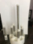
I cut a 9" pair and measured the cap same way I did above
78.45 - 78.87pF for Pos on 1/2 and 72.61 - 72.68pF for pos on 3/8"
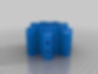
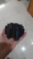
I also printed the tube holder, but holes are too loose for my pipe.
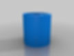
Same issue I had with cap. If the person that did the video had same problem some of the cell could be shorted out. I did play around with test print single cell in picture below and got a nice tight print. I may be able to get a tight print of holder by just changing scale of STL file before print. Did not work for cap as it made center post too small, but it may work for base as both holes are too loose about the same amount.
Picture also shows the 9" pipe and hole guide.
What size clear pipe are people using? It looks like 4" shop dust pile in the photos above should be OK for initial test, but I would recommend it for cell under pressure.
I can get schedule 40 tubes, but hole drilling guide would not fit as OD is 4-1/2"
I did purchase some stainless 1/4-20 x 1-1/2" stainless set screws with hex head to see if they will work. I also purchase stainless lock nuts.
I saw
someone else did this and just used hex head to hold springs.
I will report how well this works.

Summary Version 2 2020
Next version of 7 cell water fuel cell. Still under development.
Uses tubes with part #'s from McMaster-Carr.
89785K844 - 1/2" x 3.5" tube X 6
89785K837 - 3/8" x 4" tube X 6
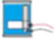
Designed to fit in a 4" ABS tube.
Use accompanying hole template to make holes in tube for the electrical contacts. Use the cap ring to isolate the middle tubes from the top.
With tube part numbers above, the gap between the tubes should be 0.7mm. With the length of the tubes indicated, the capacitance of each pair of tubes with air as the dielectric should measure approximately 43pf.
Dimensions are a very important element in the design of the water fuel cell if you want it to work the way Stan Meyer made them work. The dimensions here are according to my calculations for my system and won't necessarily work for your design.
Do your homework.
Update 2018-06-20
The original .stl for the main unit was 9mm too short. This has been corrected.
Update 2018-06-28
Updated some dimensions and corrected flaw that would prevent flow.
Update 2018-06-29
Major change. Shortened main cell body and made tube caps singles.
Tubes should fit better now.

If stainless was machined there will be cutting oil on tubes that will need to be removed. Puharich in his patent talks about running cells dry for a period as a cleaning cycle as well.
I have not been following the 9xb builds very closely. But cell builds should be the same.
The v7 cap piece that I download does not fit tight on the 1/2 pipe. The center 3/8 pipe is fit is closer. I used caliper to measure the cap and the pipe and found if I scale the cap down by 96% I got a closer fit on the 1/2" pipe but then center was now too small. I expected this to happen.
Looks like I will need to down a program to fix piece as I currently down not have a program to modify stl files. A quick look at programs looks like I will be able to do the rescale in Tinkercad. Another tools to learn how to use.
Have not cut other pipes yet as wanted to do capacitance measurements with pipes centered before cutting others. Initial measurements were done using shims.
Type 2 close to Stans Original spec.


.jpg)


.jpeg)
.jpeg)
Build Tips
If stainless was machined there will be cutting oil on tubes that will need to be removed. Puharich in his patent talks about running cells dry for a period as a cleaning cycle as well.
The v7 cap piece that I download does not fit tight on the 1/2 pipe. The center 3/8 pipe is fit is closer. I used caliper to measure the cap and the pipe and found if I scale the cap down by 96% I got a closer fit on the 1/2" pipe but then center was now too small. I expected this to happen.
Looks like I will need to down a program to fix piece as I currently down not have a program to modify stl files. A quick look at programs looks like I will be able to do the rescale in Tingercad. Another tools to learn how to use.
Oh well I bought the 3D printer to be able to do this.
Have not cut other pipes yet as wanted to do capacitance measurements with pipes centered before cutting others. Initial measurements were done using shims.
============================
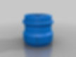
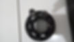
I did get cap redone using Tingercad. It was fairly easy only took a couple of tries to get measurement correct. Had problem with inside hole for 1/2" pipe being too small.
I did print cap with a brim so need a little work to remove brim to get it to fit. I am happy the way it turned out.
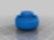
The picture below shows cap on pipes and the tools I used to clean up parts. The large tool is a pipe reamer which can be used to remove the ridge on inside of pipe when you use a pipe cutter. In this case the two small files worked better as ridge is really small but it is there.
The strips on bottom of pipe are just to keep pipe center and were made from a left-over part of another 3D print.
Next step is to print the base for the pipes and to finish cutting the other 5 pipe sets.


builder 1 with 3d print long tube cell
length of tube is 23cm for inner & outer tube, there are 0,5cm difference in length..
40 colts
tube cell 1 Capacitance Measurement = Uf 8-15 volt
tube cell 2 Capacitance Measurement = Uf 8-15 volt
tube cell 3 Capacitance Measurement = Uf84 volt
tube cell 4 Capacitance Measurement = Uf85 volt
tube cell 5 Capacitance Measurement = Uf84 volt
tube cell 6 Capacitance Measurement = Uf84 volt
Builder 2
I now have 6 cells made and did measurements on all 6. The cheap meter I am using also give the frequency being used during test if you press a button, so I included that information in reading below.
Test of 6 sets of tubes outer 1/2” x 3 ½” inner 3/8” x 4” using capacitance meter above
Outer Pos Lead Out Neg Lead
Cap in pF Freq in Hz Cap in pF Freq in HZ
1. 31.75 - 31.80 667140 29.76 – 29.80 667680
2. 31.95 - 32.01 666750 29.83 – 29.93 667444
3. 31.32 - 31.47 667160 29.71 – 29.74 667840
4. 31.95 - 32.03 667108 30.20 – 30.33 667550
5. 31.51 – 31.63 667310 30.25 – 30.33 667735
6. 31.96– 32.07 667007 30.43 – 30.57 667512
This one is with bottom spacer on both ends so inner tube sticks out both ends. I wanted to see if capacitance changed to see if this could be used to tune system.
7. 32.86 – 33.11 667540 31.19 – 31.31 667840
I am glad to see that they all appear to be fairly close in value.
Second Comparitive Builder. Same Cell
Shared but another builder
6 cells made and did measurements on all 6. The cheap meter I am using also give the frequency being used during test if you press a button, so I included that information in reading below.
Test of 6 sets of tubes outer 1/2” x 3 ½” inner 3/8” x 4” using capacitance meter above
Outer Pos Lead Out Neg Lead
Cap in pF Freq in Hz Cap in pF Freq in HZ
1. 31.75 - 31.80 667140 29.76 – 29.80 667680
2. 31.95 - 32.01 666750 29.83 – 29.93 667444
3. 31.32 - 31.47 667160 29.71 – 29.74 667840
4. 31.95 - 32.03 667108 30.20 – 30.33 667550
5. 31.51 – 31.63 667310 30.25 – 30.33 667735
6. 31.96– 32.07 667007 30.43 – 30.57 667512
This one is with bottom spacer on both ends so inner tube sticks out both ends. I wanted to see if capacitance changed to see if this could be used to tune system.
7. 32.86 – 33.11 667540 31.19 – 31.31 667840
the frequency is 667140 (six hundred sisxty seven ty thousand and one hundred forty)
not 667.14 (six hundred sixty seven point forteen)
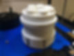
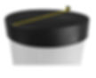
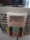
Test setup to check capacitance of tubes.
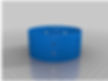
I made a spacer ring that fits over the bottom of tubes to center the 3/8” tube inside the 1/2” tube so I could get a more accurate reading of the capacitance of the cell.
Note: I made spacer so I could do these tests and to obtain size of holes in base I need use when I print the base.
The meter I am using needs to be re-zeroed before each measure which requires leads to be disconnected. I also found when I did some initial tests with shims that holding leads affects reading which is why I used rubber band to hold lead to outer tube. I also noticed that the readings were different when I reversed leads but found difference to be much less using the rubber band. The red lead is positive and black lead is negative.
I did repeat the test several times and similar results.
First picture shows items being used
1/2” tube 3 ½” long
Top cap
Bottom spacer
3/8” tube 4” long
Rubber band to hold meter lead on outer tube
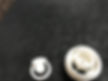
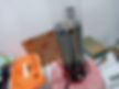
Second picture shows meter reading and test setup with positive lead of meter on inner tube
Third picture shows meter reading and test setup with negative lead of meter on inner tube
Final note while meter never completely settles down with this setup difference in readings are much smaller in range of a few tenths of pf.
Next step is cut more tube sets and repeat these tests.
Earl


