GO Faster Go Further
Established since 2001

Hydrogen Hot Rodding™ ©

Secure Supplies Group


Stanley A Meyer VIC Resonance

The Information is here, we have gone to great lengths to show the information. If you study how to test resistance resonance in your coils chokes and water cells before assembly it will help you to gain the insights needed to assemble correctly and understand the methods.
Many a Person has missed the opportunities for guidance.
Your Support us we Support you .
Stanley A Meyer
Dual-Inline RLC Network

To Understand How this works you need to experiment and test with a Sinusoidal Generator
Here is example Circuit

Types of LC Circuits


Now we Connector 2 Inductor's and Diode
( Diode Between Ca inductor and Capacitor)


Now we Add a 1 Kilo Ohm Resistor in Parallel to the WFC/ Capacitor to examine the signals


So We See that now that the Resistor is effecting the resonance, (Stan Must have used it as a adjustment to balance resonance back) For example in the case that cell has a dbd barrier or layer of glass for example. which would cause a imbalance by which the resistor rebalances


How to Work with
"Cold Resonance":
Study More

How to work "Cold Resonance":
https://www.youtube.com/watch?v=zilvq...
https://www.youtube.com/watch?v=EYVv8...
https://www.youtube.com/watch?v=A2eJf...
My circuit diagram:
http://alfa.kachi-snimka.info/images-...
My Bifilar Inductor on Ferrite E-Core
http://prikachi.com/images/287/790128...
Memo WFC 420 http://www.sentex.ca/~mec1995/hho/Mey...
Dr. Andrija Puharich`s Patent for "Water Decomposition by AC Electrolysis": http://www.rexresearch.com/puharich/1...
Patent GB 2.324.307A - Electrostatic Electrolyse method http://www.tuks.nl/pdf/Patents/Eccles...
SHOW LESS
How to Measure Resonance in a Hydrogen HHO Water Cell

Stanley Meyer is absolutely right! The Water not have "Resonance frequency", but the Water Cell have "Self Resonance frequency" !
In this experiment i use one 4-inch Cell. Distance between the Electrodes is about 2.5 mm. Water Conductivity - 113 µS/cm. !!!!!
Note, the Yellow Channel Wavegorm (Generator`s output): 14:30 minute, at 7.3 MHz !!!!!
As you see, this is "known waveform" of SERIAL RESONANCE !!!
Stanley Meyer's Patent EP0103656A2: https://www.google.com/patents/EP0103...
My circuit diagram: http://prikachi.com/images/987/894398...
Link to a similar research:
http://www.intechopen.com/books/elect...
The key to understand Stanley Meyer's technology, is a "Resonant waveform", presented in the Patent US 2005/0246059 A1, of
Stephen Meyer (Stanley Meyer's twin brother).
he key to understand Stanley Meyer's technology, is a "Resonant waveform", presented in the Patent US 2005/0246059 A1, of Stephen Meyer (Stanley Meyer's twin brother). Stephen Meyer`s Patent US 2005/0246059 A1: https://drive.google.com/open?id=1_0f...
My Circuit diagram: https://drive.google.com/open?id=14sE... Used values: Resonant frequency - 789 kHz !!!! (This is not a joke) Gate frequency - 31.5 kHz !!! Gate "Duty/Cycle" - 28 % Bifilar inductor - 2 x 100 turns, 0,5mm., copper wire on ferrite core.
The Signal to the Primary coil is "Inversed" Pulse train" !!!! (like at Meyer`s VIC!) The Self Resonant frequency of the Bifilar inductor, at "1:1 Resonance" is about 43 kHz. Very important!!!
Note, that the "Gate generator" (Low frequency generator) must be tuned about 27 % less than "Self Resonant frequency" of the Bifilar inductor /43 kHz - 27 % = about 31 kHz/!!! Then, "High frequency generator", may be at 500 kHz to 1,5 MHz !!!! !!!!!!!!!!!!!
Stephen Meyer`s Used values: Resonant frequency - 13,5 kHz Gate frequency - 496,9 Hz Gate "Duty/Cycle" - about 40 % The the Internet, ago has info that Stanley Meyer uses the following values: Resonant frequency - 42.8 kHz Gate frequency - 600 Hz Gate "Duty/Cycle" - 50%
And, a very interesting fact: "Recently we learned that the Water Disrupting Spark Plug promoted around 1994 by Stan Meyers was in fact suggested to him by Dale Pond at a conference in Switzerland back in 1989.
The idea was you should be able to use Keely's 42.8khz emitted from a spark plug to instantly dissociate the water molecule to hydrogen and oxygen which would then be exploded to drive the piston." Another, successful replication of the Stephen Meyer`s Waveform, from Tony Woodside: https://www.youtube.com/watch?v=cX6yY...
Stanley Meyer's WO 92/07861: http://www.rexresearch.com/meyerhy/wo... "In the invention, the adjustable frequency generator (Figure 12) /Gated generator/, tunes into the resonant condition of the circuit including the water cell and the water therein."!!!!!
"Shape and size of the resonant cavity may vary. Larger resonant cavities and higher rates of consumption of water in the conversion process require higher frequencies such as up to 50 KHz and above. The pulsing rate, to sustain such high rates of conversion must be correspondingly increased."!!!
"Also, at a resonant condition harmonic effects occur. In a typical operation of the cell with a representative water capacitor described below, at a frequency of about 5 KHz at unipolar pulses from 0 to 650 volts at a sensed resonant condition into the resonant cavity, conversion of about 5 gallons of water per hour into a fuel gas will occur on average. "!!!
Stephen Meyer`s Waveform replication
•2 Sep 2018
Water Resonance Waveform
•7 Oct 2018
_JPG.jpg)
The key to understand Stanley Meyer's technology, is a "Resonant waveform", presented in the Patent US 2005/0246059 A1, of Stephen Meyer (Stanley Meyer's twin brother).
Stephen Meyer`s Patent US 2005/0246059 A1: https://drive.google.com/open?id=1_0f...
My Circuit diagram: https://drive.google.com/open?id=19r4...
Bobbins on Air core - 0,3mm. copper wire,
Bifilar wrapped: https://drive.google.com/open?id=1rdq...
Another, successful replication of the Stephen Meyer`s Waveform, from Tony Woodside: https://www.youtube.com/watch?v=cX6yY...
Stanley Meyer's WO 92/07861: http://www.rexresearch.com/meyerhy/wo...
"In the invention, the adjustable frequency generator (Figure 12) /Gated generator/, tunes into the resonant condition of the circuit including the water cell and the water therein."!!!!!
"Shape and size of the resonant cavity may vary. Larger resonant cavities and higher rates of consumption of water in the conversion process require higher frequencies such as up to 50 KHz and above.
The pulsing rate, to sustain such high rates of conversion must be correspondingly increased."!!! "Also, at a resonant condition harmonic effects occur. In a typical operation of the cell with a representative water capacitor described below,
at a frequency of about 5 KHz at unipolar pulses from 0 to 650 volts at a sensed resonant condition into the resonant cavity, conversion of about 5 gallons of water per hour into a fuel gas will occur on average. "!!!
Bobbins on Air core - 0,3mm. copper wire, Bifilar wrapped:

How to Learn what Resonance is >?
These Circuit are mentioned in this video so I put them here so you can compare to your work


_JPG.jpg)


In the invention, the water capacitor is subjected to a duty pulse which builds up in the resonant changing choke coil and then collapses.
This occurrence permits a unipolar pulse to be applied to the fuel cell capacitor. When a resonant condition of the circuit is locked-in by the circuit, amp leakage is held to a minimum as the voltage which creates the dielectric field tends to infinity.
At start up, in this example, current draw through the water cell will measure about 25 milliamp; however, when the circuit finds a tuned resonant condition, current drops to a 1-2 milliamp minimum leakage condition.
In a typical operation of the cell with a representative water capacitor described below, at a frequency of about 5 KHz at unipolar pulses from 0 to 650 volts at a sensed resonant condition into the resonant cavity, conversion of about 5 gallons of water per hour into a fuel gas will occur on average.
The diode is an electronic switch that determines the generation and collapse of an electromagnetic field to permit the resonant charging choke(s) to double the applied frequency and also allows the pulse to be sent to the resonant cavity without discharging the capacitor therein.
The transformer core is a pulse frequency doubler.
My Circuit diagrams:
https://drive.google.com/open?id=0Bxn...
https://drive.google.com/open?id=0Bxn...
https://drive.google.com/open?id=0Bxn...
https://drive.google.com/open?id=0Bxn...
Stanley Meyer`s WO 92/07861:
http://www.rexresearch.com/meyerhy/wo...
https://drive.google.com/open?id=0Bxn...
https://drive.google.com/open?id=0Bxn...
https://drive.google.com/open?id=0Bxn...
My Circuit diagram: https://drive.google.com/open?id=1qE7... In this Video,
i use only Resistor 220 ohm/10 Watts to the Primary coil! Diode to the Primary coil is not connected - it is "destroying" the Correct Waveform.

The key to understand Stanley Meyer's technology, is a "Resonant waveform", presented in the Patent US 2005/0246059 A1, of Stephen Meyer (Stanley Meyer's twin brother).
"In the invention, the adjustable frequency generator (Figure 12) /Gated generator/, tunes into the resonant condition of the circuit including the water cell and the water therein."!!!!! "Shape and size of the resonant cavity may vary. Larger resonant cavities and higher rates of consumption of water in the conversion process require higher frequencies such as up to 50 KHz and above.
The pulsing rate, to sustain such high rates of conversion must be correspondingly increased."!!! "When a resonant condition of the circuit is locked-in by the circuit, amp leakage is held to a minimum as the voltage which creates the dielectric field tends to infinity."
Stephen Meyer`s Patent US 2005/0246059 A1: https://drive.google.com/open?id=1_0f...
In this Video, i use only Resistor 220 ohm/10 Watts to the Primary coil! Diode to the Primary coil is not connected - it is "destroying" the Correct Waveform.
Stanley Meyer's vs.
Stephen Meyer`s Circuit diagrams: https://drive.google.com/open?id=1uur...
https://www.youtube.com/watch?v=cX6yY... Andrija Puharich`s Patent US4394230A: https://patents.google.com/patent/US4... Stanley Meyer's WO 92/07861: http://www.rexresearch.com/meyerhy/wo... Bobbins Connection circuit diagram Source: https://drive.google.com/open?id=1tVn... Ferrite Core (FERROXCUBE U93/76/16-3C90) Website: https://www.tme.eu/en/details/u93_76_... Link to "My Home-made Oscilloscope High-Voltage probe 1000:1" https://www.youtube.com/watch?v=Cwwt7...
Water Resonance waveform with Bifilar Inductor
Link to my previous Video: https://www.youtube.com/watch?v=Bw4AD...
This Oscilloscope screenshot is VERY IMPORTANT !!!!! https://drive.google.com/open?id=1Ejq...
It is presented by Stephen Meyer in his Patent US 2005/0246059 A1, but this WATER RESONANCE WAVEFORM is achieve from his twin brother - Stanley Meyer. For this Resonant waveform
Stephen Meyer say: "FIG. 6 shows the high-frequency ringing signals that contribute to the operation of the hydroxyl production. Just as a tuning fork rings when struck by a hammer, so does the wave-guide elements in arrays 132 immersed into the hydroxyl generating liquid 133 then struck by the electrical signals FIG. 5,6 from impedance matching circuits 102 depicted in FIG. 4.":
More precise determination of Pulse-train`s "Duty cycle" - 40% : https://drive.google.com/open?id=1BJq...
My Circuit diagram: https://drive.google.com/open?id=1odx...
How the Diode and the Resistor affect the "shape" of the Resonance Signal: https://drive.google.com/open?id=1P9S...
Stanley Meyer and his twin-brother Stephen Meyer:
https://drive.google.com/open?id=1LCw...
Stanley Meyer's vs. Stephen Meyer`s Circuit diagrams: https://drive.google.com/file/d/1uurP...
Stanley Meyer's vs. Andrija Puharich`s Circuit diagram:
https://drive.google.com/open?id=1wnQ...
Stephen Meyer`s Patent US 2005/0246059 A1: https://patents.google.com/patent/US2...
Andrija Puharich`s Patent US4394230A: https://patents.google.com/patent/US4...
Stanley Meyer's US4936961A: https://patents.google.com/patent/US4...
"The step-up coil is formed on a conventional torroidal core formed of a compressed ferromagnetic powdered material that will not itself become permanently magnetized, such as the trademarked "Ferramic 06# "Permag" powder as described in Siemens Ferrites Catalog,CG-2000-002-121, (Cleveland, Ohio) No. F626-1205.
The core is 1.50 inch in diameter and 0.25 inch in thickness. A primary coil of 200 turns of 24 gauge copper wire is provided and a coil of 600 turns of 36 gauge wire comprises the secondary winding. ...In the circuit of FIG. 1, the diode is a lN1198 diode which acts as a blocking diode ...
As the stepped-up pulse enters first inductor (formed from 100 turns of 24 gauge wire 1 inch in diameter)..." Stanley Meyer's WO 92/07861: http://www.rexresearch.com/meyerhy/wo...
"At start up, in this example, current draw through the water cell will measure about 25 milliamp; however, when the circuit finds a tuned resonant condition, current drops to a 1-2 milliamp minimum leakage condition."
"Also, at a resonant condition harmonic effects occur. In a typical operation of the cell with a representative water capacitor described below, at a frequency of about 5 KHz at unipolar pulses from 0 to 650 volts at a sensed resonant condition into the resonant cavity, conversion of about 5 gallons of water per hour into a fuel gas will occur on average. "!!!
"In the invention, the adjustable frequency generator (Figure 12) /Gated generator/, tunes into the resonant condition of the circuit including the water cell and the water therein."!!!!!
"Shape and size of the resonant cavity may vary. Larger resonant cavities and higher rates of consumption of water in the conversion process require higher frequencies such as up to 50 KHz and above. The pulsing rate, to sustain such high rates of conversion must be correspondingly increased."!!!
"When a resonant condition of the circuit is locked-in by the circuit, amp leakage is held to a minimum as the voltage which creates the dielectric field tends to infinity."
Signal Synchronization (EN): https://www.youtube.com/watch?v=kNfBm... Синхронизация сигналов: https://www.youtube.com/watch?v=wmL3j...
That is very interesting - Water Resonant Waveform vs. Heart monitor Waveform /ECG signal with visible TWA/ https://drive.google.com/open?id=1tfz...
And for the finale - a interesting story from Russia. Ten years ago... Translate the site into your language using Google Translator and read it!
And when your friends ask you, why they still do not see a cars,
running on water - tell them... http://3rm.info/main/71199-vechnye-dv...
Signal Synchronization Signal synchronization is a standard procedure of signal timing. It may be provided by triggers.
A trigger is the easiest device used to avoid spurious pulses of combinational circuit output which occur if several input signals are changed almost at the same time. In this case the synchronization requires a delayed sync signal transmitted with input data signal (or input code).
A delay time shall exceed the delay time of the combinational circuit by t3. You can receive a signal without any spurious pulses by transmitting sync signal to C output of the trigger and output signal of the combinational circuit to D input of the trigger. If input code of a combinational circuit is changed on a regular basis, sync signal front may match input code change. In this case, signal will be transmitted to C input of the trigger earlier than D input signal will be changed due to the final delay factor of the combinational circuit. The trigger will not register any spurious pulses.
In this case, trigger output signal will be delayed within the transmission period of T input code (or sync signal) towards output signal of the combinational circuit. Designed digital circuit operating according to timing signal generated by one clock generator often requires synchronization with any external signal. It means that you shall provide external signal changing according to timing signal of the clock generator. In this case, trigger may be used. Let's consider the simple example.
Let transmission of clock generator signal is enabled or restricted by an external signal. In the simplest case, 2I logical element is used to enable or restrict clock generator signal. Herewith, reduced or minimum pulses as well as unstable pulses may be transmitted to circuit output which may result in circuit uncertainty. Synchronization trigger transmits only full length pulses to 2I logical element output.
Enabling signal transmitted through the trigger and timed with the enabling signal is synchronized with a clock signal and provides transmission of full length pulses and full clock generator periods to the output.
My Circuit diagram:
https://drive.google.com/file/d/1Gb-TgQWv9_GosEl8YFWnt1GmLS9AVyal/view

This Oscilloscope screenshot is VERY IMPORTANT !!!!!
https://drive.google.com/file/d/1EjqGYtkIZqP9ZDdJQ4CgyyPABykSelFy/view

More precise determination of Pulse-train`s "Duty cycle" - 40%
How the Diode and the Resistor affect the "shape" of the Resonance Signal

That is very interesting - Water Resonant Waveform vs
. Heart monitor Waveform /ECG signal with visible TWA/

Stanley Meyer's vs. Stephen Meyer`s Circuit diagrams: https://drive.google.com/file/d/1uurP...
Mistakes Corrected in Stephen Meyer`s RESONANCE Impedence Matching Circuit A Voltage Doubler with Inductors 21 Mar 2020


My Excel table calculator:
https://drive.google.com/open?id=18EP...
It is presented by Stephen Meyer in his Patent US 2005/0246059 A1, but this WATER RESONANCE WAVEFORM is achieve from his twin brother - Stanley Meyer. For this Resonant waveform Stephen Meyer say: "FIG. 6 shows the high-frequency ringing signals that contribute to the operation of the hydroxyl production. Just as a tuning fork rings when struck by a hammer, so does the wave-guide elements in arrays 132 immersed into the hydroxyl generating liquid 133 then struck by the electrical signals FIG. 5,6 from impedance matching circuits 102 depicted in FIG. 4.":
Stephen Meyer`s Patent US 2005/0246059 A1: https://patents.google.com/patent/US2...
https://drive.google.com/open?id=19_n...
Andrija Puharich`s Patent US4394230A: https://patents.google.com/patent/US4...
Stanley Meyer's US4936961A:
https://patents.google.com/patent/US4...
"The step-up coil is formed on a conventional torroidal core formed of a compressed ferromagnetic powdered material that will not itself become permanently magnetized, such as the trademarked "Ferramic 06# "Permag" powder as described in Siemens Ferrites Catalog,CG-2000-002-121,
(Cleveland, Ohio) No. F626-1205. The core is 1.50 inch in diameter and 0.25 inch in thickness. A primary coil of 200 turns of 24 gauge copper wire is provided and a coil of 600 turns of 36 gauge wire comprises the secondary winding. ...In the circuit of FIG. 1, the diode is a lN1198 diode which acts as a blocking diode ...
As the stepped-up pulse enters first inductor (formed from 100 turns of 24 gauge wire 1 inch in diameter)..."
Stanley Meyer's WO 92/07861: http://www.rexresearch.com/meyerhy/wo... "At start up, in this example, current draw through the water cell will measure about 25 milliamp; however, when the circuit finds a tuned resonant condition, current drops to a 1-2 milliamp minimum leakage condition." "
Also, at a resonant condition harmonic effects occur. In a typical operation of the cell with a representative water capacitor described below, at a frequency of about 5 KHz at unipolar pulses from 0 to 650 volts at a sensed resonant condition into the resonant cavity, conversion of about 5 gallons of water per hour into a fuel gas will occur on average.
"!!! "In the invention, the adjustable frequency generator (Figure 12) /Gated generator/, tunes into the resonant condition of the circuit including the water cell and the water therein."!!!!!
"Shape and size of the resonant cavity may vary. Larger resonant cavities and higher rates of consumption of water in the conversion process require higher frequencies such as up to 50 KHz and above.
The pulsing rate, to sustain such high rates of conversion must be correspondingly increased."!!! "When a resonant condition of the circuit is locked-in by the circuit, amp leakage is held to a minimum as the voltage which creates the dielectric field tends to infinity."
A very interesting fact: "Recently we learned that the Water Disrupting Spark Plug promoted around 1994 by Stan Meyers was in fact suggested to him by Dale Pond at a conference in Switzerland back in 1989.
The idea was you should be able to use Keely's 4.8khz emitted from a spark plug to instantly dissociate the water molecule to hydrogen and oxygen which would then be exploded to drive the piston."
And for the finale - a interesting story from Russia. Ten years ago...
Translate the site into your language using Google Translator and read it! And when your friends ask you, why they still do not see a cars, running on water - tell them... http://3rm.info/main/71199-vechnye-dv...

WELCOME TO 2020
and Beyond
Lets use some new
Tools Boys and Girls
Designing a Broadband Amplifier with a 3D Smith Chart
In this video clip, Matt Ozalas talks about how to visualize and understand simulation data.
Matt shows an example of how to design a broadband amplifier
with a 3D Smith Chart.
Register for the entire webcast at: https://www.keysight.com/main/eventDetail.jspx?cc=TH&lc=eng&ckey=2791771&nid=-34335.804578.08&id=2791771
Apply for a FREE Trial of ADS at: https://edaapps.software.keysight.com/cgi-bin/eda-evaluation/request.cgi?es=ads-rfmw-video&product=ads&cc=zz&lc=eng
So we have many amazing Communications devices and engineers, it is now time to employ them and complete the auto tuning design of
Stephen and Stan Meyer
s
Double Distilled Water
As Crude Oil is not a Car fuel,
so Tap Water is not a Car fuel,
but Gasoline and Double-Distilled Water - is!
About 20 years ago in scientific journals a article appeared in a publication, in which it describes a Car,
that ran only on Water Fuel.
The Car engine use absolutely, extremely clear water.
A Indication, that the Car Driver used only one of the car seats, because other three places are occupied ...
by Distilling equipment ... and i never again read about this success... nowhere ...
The first Stanley Meyer's Electrolysers
(like 8XA Circuit diagram with Long Tube Set) directly work with Tap Water! And this is correct!
But "Resonance" Electrolyzers
(like 11-Tube Cell and Water Injector) work only if is use Double-distilled Water!
If the Water has excessive "Resistance",
Resonance condition is not created - VIC-Transformer will not work!

How to Stanley Meyer present "Water Resistance" of Cell: http://prikachi.com/images/263/801426...
http://en.wikipedia.org/wiki/Purified... Stanley Meyer`s Patent US 4,936,961 A: http://www.google.com/patents/US4936961


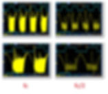
Here is 3 types of Water (left to right):
Once Distilled water from Factory Distiller Deionized water from Gas Station Purified water from Pharmacy
http://prikachi.com/images/116/801411...
Once-Distilled Water have Electrical conductivity about 2.2 μS/cm (Microsiemens Per Centimeter)
Double-Distilled Water have Electrical conductivity about 1.6 μS/cm (Microsiemens Per Centimeter) -
Sea Water – 5 (S•m-1) -
Tap Water – 0.0005 – 0.05 (S•m-1) -
Distilled Water – 5.5 x 10⁻⁶ (S•m-1)
The Electrical conductivity of Water is measured with device
"Conductivity Meter": https://www.google.bg/search?q=Conduc...
How to calibrate Conductivity Meter: https://www.youtube.com/watch?v=eHWPf...
Perfect "Once-Distilled Water must have Electrical conductivity about 2.2 μS/cm
(Microsiemens Per Centimeter)
Double-Distilled Water must have Electrical conductivity about 1.6 μS/cm
(Microsiemens Per Centimeter)
Distilled Water`s Thermal energy: http://prikachi.com/images/519/802951... Stanley Meyer's Memo WFC 420: http://www.sentex.ca/~mec1995/hho/Mey...
In Memo WFC 420 (Page 1-3) Stanley Meyer say: "Voltage intensity or level across Excitor-Array (ER) can exceed 20,000 volts" . Stanley Meyer's Memo WFC 425: http://waterpoweredcar.com/pdf.files/...
In Memo WFC 425 (Page 6-2) Stanley Meyer say: "All activation points (E9a - b - c - d) performing their respective functions in sequential order in an instant of time since applied voltage level of intensity (typically 20,000 input volts or so) can be extended or increased up to and beyond 90,000 volts range within a millisecond or less". Stanley Meyer's Memo WFC 426: http://waterpoweredcar.com/pdf.files/...
In Memo WFC 426 (Page 7-1) Stanley Meyer say: "The "mode-of-operability" of VIC Coil Assembly allows Voltage Potential of opposite voltage polarity to increase and be attenuated up to and beyond 20 Kilovolts while inhibiting and restricting amp leakage in the milliamperes range ..." WO 92/07861 http://www.rexresearch.com/meyerhy/wo...
In WO 92/07861 Stanley Meyer say: "At start up, in this example, current draw through the water cell will measure about 25 milliamp; however, when the circuit finds a tuned resonant condition, current drops to a 1-2 milliamp minimum leakage condition."
SHOW LESS

Finally!!! At first time, the Real Stanley Meyer's VIC-Resonance.. is visible !!!
Input Power - 150 Volts DC / 70 mA. = 10,5 Watts !!! (It's not a joke!)
Output Power - 2000 Volts /2 mA = 4 Watts. My Circuit Diagram "Half-bridge Driver" like computer's ATX Power supply: http://alfa.kachi-snimka.info/images-...
FERROXCUBE U93/76/16-3C90 - Ferrite Core Website: http://www.tme.eu/en/details/u93_76_1...
High voltage Teflon insulation tape (must use, you see what happens without insulation!): https://www.pentod.com/product/44/tef...
Here, in this my previous video - how to look usual DC Electrolyse - Voltage about 2000 Volts, applied to same
Double Distilled Water Capacitor: https://www.youtube.com/watch?v=HwkKn...


Testing PLL 2020
I made a couple of changes to my boards. To give me finer control of frequency I changed the dial pot on the Phase Lock Circuit (K21) to a trim pot and moved LEDs to front panel.
This also gave me slightly more range as well as I can now get above 10khz.
This turns out to be helpful in finding and setting the resonant points.
Other change was to put additional capacitors on both 5vdc and 10vdc power feeds to boards. I did this as I was seeing large spikes in the analog signal that also blend over in digital when they are merged across the Primary coil.
The spikes also caused both signals to jump around which has mostly stopped. I have also ordered a better DC power supply.
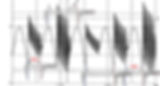
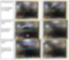
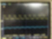
Pictures below are after making these changes which both helped a lot. Part of this testing was to see the effect of the changes and I was also trying to see how the signals changed with frequency. In these pictures I have also switched the scope probes to be AC coupled.
Pictures P1-p2 show the capacitor being charged P1 is around 2K and P2 3K. P3 is approx. 4k and zoomed in to Half on one gate pulse.
P4 is in sync at 7.333khz. In this picture CH1 is on input to primary and you can see analog pulse out of L1 into cell being inside of the single Digital pulses on primary inputs. Note: when I switch CH1 to L2 input to cell board loses sync (so scope effects readings). Additional note. The 2 lower signals is more like what I am seeing when I use the differential probe.
Picture P5 is one gage pulse with signals in sync and P6 show both signals when you zoom way in.
Yellow is CH1 on side L2 side or Digital input to Primary, Blue is CH2 all on analog side L1 and Purple is the Math function of scope A-B where CH1 is A and CH2 is B.
One of the reasons of doing this series of tests was to give me a new baseline with cleaned up signals. I was also was watching changes to differential signal as my new differential probe arrived today. While I played with new probe after it arrive not ready to post results yet. I will do that in another post. It does provide a must cleaner signal to scope.
One note you do lose the sync information in P6 with the differential probe. But with the cleaner signals I am finding the sync light on K21 is working.
Note: All these tests where done with the same gain and offset values which were both just set above what I think are the minimum values to keep changes to the system to be just frequency in this case. I will note that in the past I have see a resonant point at lower frequency with a higher offset. I have read that this may be due to more energy in the harmonics.
I purchased a MIcsig DP2003 High Voltage Differential Probe (Approx. $240).
It has 2 ranges 560V(200x) and 5600V(200x) as I want to be able to check cells with higher.
The have another model the Micsig DP1003 with 50x/500x up to 1300V would have been a better match to my O-scope as it has a 50x range. The one I purchased works great, but the voltage displayed is low by a factor of 2. When I was looking for probe,
I saw reviews that said O-scope would just to range of probes or you could download new ranges, however, that did not work for my older scope. I will try to make note of this when I post scope pictures, so people know value for it on screen is incorrect.
As the differential probed does not use the system ground it give a true reading on the voltage across the interface to the cell and very clean signal as all the common mode noise is removed. In screen shots I set the probes to show the pulses up to match the signal going into primary coil which I am using as frequency reference, you can do this by either moving the probes or using invert function of scope. This is for display purpose only as the only signal the cell sees it the one on cell interface.
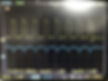
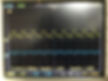
The pictures below show my next series of test. I repeated the above testing but added a few more tests points at I wanted to capture points where the signal made a change. Input analog signal set to minimum gain and offset.
Analog frequency and gate is approximately 41hz and gate has 50% duty cycle. Only the frequency was changed pictures show the digital input to primary in yellow on CH1 which I used to set frequency and provide a reference signal for the CH2 blue which is from the differential probe on the cell interface
(In this case a capacitor and resistors to provide load, no cells so sync reading will be off from complete system).
NOTE: The differential probe reading on scope is low by a factor of times 2 as probe scale does match scopes.
Goal is to see how the differential signal changes as frequency changes. In most case the table show the signal zoomed in on one digital pulse in the left table cell and the right show same signal zoomed out so you can see either complete gate pulse or multiple pulses with gates shown.
Couple of exceptions P1 and P24 are in the first row of one table and last few rows of second table show a few special items. Dan P24 is close to the signal in the YouTube videos you recommended I look at to see what resonance signal looks like.
The shape of the signal on the cell changes with frequency as expected. It ramps up as the capacitor charges, but shape of ramp varies depending on the phasing of the digital and analog inputs.
The zoomed signal shows that the number of pulses in each digital pulse varies with frequency in pictures below they varies from a high of 6 at 700hz to 1 at 11khz. The position of the pulses also changes which I believe also effects the shape of each Gate Pulse. You can see this it the second picture in each row.
In some case you can see the charge of the capacitor ramp up then level off for the rest of the gate pulse. At select points the ramp is a straight slope P23 but getting that is very touchy and usually happen just before signal is in resonance. Usually shortly before that happens there is sag in the startup ramp see P23.
When the signal is resonance the differential signal is a straight line P20 and P21.
Also, at 5khz P14 and P15 while not complete zero the differential signal is flat with no ramp up charge.
P18 and P19 show what happens when I slightly increased frequency above 5khz where the output signal was flat. Look closely at these 2 pictures in P18 you can see the input frequency jumping around and in P19 where I change it slightly input frequency levels off, but you can see a ramp in top of blue signal.
Ronnie has stated you do not want to be in exact resonance but slight off, I wonder it the point where you have the straight slope could be the point he is talking about (P13 and P22).
I also wonder is you are at point where the signal ramps up then levels off would like they charge you can get on the cells, see P23 it show the leveling off that I am talking about. This happens at several other points as frequency increases.
While I do not show it here, I did do a quick check to we what would happen if changed offset.
Did this test at 5khz. To see this, I turned DC coupling on both scope channels, and moved CH1 to analog input to primary and put scope sync on CH2 as it had a nice clean pulse.
By doing this I was able to see both the analog input and differential output change. The levels on both stayed in sync and moved the same amount on the scope. I plan on doing more testing on to very nothing else changes, but this is what I expected to happen.
While this is what I expect the signals should look like the values I am getting are for my test setup and I expect they will be different for an operational system. At this point I am still trying to understand what the controls do.
NOTE
Nice to see some cleaner signals etc, but we should all note we must stay under 10kz in my opinion
Stan did mention this i will try to find the reference. Note that capacitance and smoothing can be gain in the cell design rather than circuit
so be careful not to over engineer the circuit when no cell attached


Understand and I agree which is why I added caution about this been a test configuration. Ronnie repeated mentions you need to design to cells.
The high frequency came because the trim pot has more range. I know my system coils are not set up properly but did not want to make changes until I could see the results of the those changes.
I think with the cleaner signals I should be able to do that now. One thing I did not point out is in some of my earlier testing I did see solid resonant lock at lower frequencies with higher offsets. Note: 11khz is at the top end of the range of Stan's circuit after that you lose all signals.
Also before I start to balance chokes I wanted a better idea of what is a good figure for the capacitance of the cells. One of the reason I was looking at dielectric values and trying to understand how they change as cell is charged.
I also expect that once set frequency will not be changed often as the control for this in on a pot on the Vic board not on the front panel.
My next step is very that signal shape does not change when you set the frequency and change the offset. I will do this at several points. I have already did that for 5khz as I mentioned above so I believe will also be true at other points but I will do tests to verify.
After those test I plan on doing more test on changing number turns on choke just to see what that does to signal. Will all change gape again to see what it does to signal.
Before all I did was measure the H change of coils.
Dan I have been looking at things from Ronnie's post in this thread .
"Understanding How Stan Meyers Fuel Cell Works"
« on October 22nd, 2016, 04:13 AM »Last edited on October 23rd, 2016, 05:58 PM
He talks in the first few posts about how resonance should be designed to occur when cell is empty of water and it should occur around 11 volts. Several post later he talks about how the coils should be set to create a signal that is out of phase.
Phasing is one of things I am trying to understand and figure out how to test.
He also states people are looking at frequency doubling wrong as it should only occur after resonance.
He even talks about changing cells capacitance when using Fifo;ar-warp chokes as way to balance system when using this method.
I think I need to read this thread again as I have a better understanding of what he was trying to tell us.
Just finished rereading by condensed version of "Understanding How Stan Meyers Fuel Cell Works". I get something out it every time I read it in part because I not understand better what they are saying.
In this case the things Ronnie says about tuning were very helpful as I am the process of trying to understand the steps to do that. One of the things that has been bothering me was the 1.23V differential he said was need across the cell to keep water polarized.
I had remembered value but forgot that it was the DC offset which is always applied to cell anytime power is on. So when cell is turn off the offset is still there (cell can be off buy power on).
This offset sets the voltage that keeps the charge on the plates balance 2+ H ions to 1- O ion.
I was trying to figure out how to measure this when power to cell was increasing but it does not apply then.
There is discussion in this thread on turns ratio, adjusting phase angle, what gap does, and that they need to tuned to get max power out of the system.
Bad new is changing one effects others so it a balancing act. While I knew that my test system was different that operating system as I am using a capacitor and not a water cell, Ronnie points out that the systems operate differently before and after resonance.
He says we have a dead short with water in cell that blocks the coils from fully interacting before resonance. After resonance the short is removed and only then do they interact and we get frequency doubling.
Until then we are using amp leakage to create gas and when there is enough gas under then we get resonance.
Note: I have posted my condensed version of this thread in a PDF document and it is still 110 pages long. Post above is actually out that document. It has links back to original thread imbedded.
I do plan to continue with my current testing a am continuing to learn more about the system and obtaining a better understanding of what happen when I make a change.
One thing he did method briefly it is better to do initial turning in air manually. By that he means without using the phase lock circuit. I can see why in my testing once you get close to a phase lock it is hard to make a frequency change. (See reference below)
Re: "Understanding How Stan Meyers Fuel Cell Works"
« Reply #444, on November 4th, 2016, 06:14 PM »
Quote from ~Russ on November 4th, 2016, 06:03 PM
I would call it a variable in our math, aka we need to know theses as even frequency play's a BIG roll on the capacitance.
~Russ
Exactly, Now you and others wanted to know how to tune the system.
What I am about to say and show is for manual tuning only, with no feedback coil or phase lock loop device.
I have stated many times you have to start out at a couple volts and work your way up a couple volts at a time while tuning until you reach full voltage.
What I am about to show everyone is how to use a fixed L to tune into a variable C It is all done by frequency.
==============
Dan it is already posted in WFC - Collection of Posts From 2 Huge Treads About How WFC Works
Collection of Posts from Stans Vic Reverse Engineered and ready to build thread.pdf
Collection of Posts from Stanley Meyer Works Thread.pdf
There are 2 PDFs attached. (You should already have them as you asked me to put them into PDF instead of word documents).
There were 2 huge threads where Ronnie and others talked about designing VIC I copied what thought were the most important ones into these two documents. When I reference a topic I generally get reference out these documents as I can quickly scan through them.
As both documents have the links back to the original threads you can quickly go to them and see other discussions around them who made post. The posts with Re: highlighted in green are Ronnie's. Please note: I did not generate the information only collected it together for my own use. I have made minor edits to make easier to read mostly spelling etc.
Between these two threads there are examples of all the math needed to balance impendence and resistance plus a lot hints about what works and why.
This is not short the work of others as I have read most all the other threads and made use of the information in them.
Ronnie talks about tuning around resonance frequency to get max power into system.
I have noticed in my testing that while it looks like there should be a sync point around 5khz,as you can see in picture above the lock like does not come at when at low power.
However, I have seen it come on when I was testing high power though getting it to do that was a very minor change in frequency. Only notice this as I had set frequency at 5khz and only changed gain.
As I mentioned above I could get my board to sync at lower frequency with a high gain setup.
So I tried to do it again. Start with 5khz and turned up offset to high level (still not sure best way to measure that).
I was watch in output of differential probe on cell and Digital input to Primary.
They stayed in sync but board did not lock when I zoomed out the shape was not the sync shape so I reduced the frequency until out put differential probe looked right and board lite lock light lite up (I remember when I did this before sync was below 5khz and is at 3.788khz).
Note: my test system cokes are not correctly balanced and just using a capacitor for load.
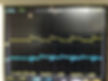
The 4 pictures below show the signals when board is in sync.
CH1 - Yellow is the Digital signal into Primary coil and my reference signal
CH2 - Blue is the differential signal into Capacitor
Scope on CH1 and CH2 set to AC coupling
First picture is a looking inside a gate pulse at the individual pulses
Second picture same setting except zoomed out to see multiple gates pulses
Scope on CH1 and CH2 set to DC coupling - allows me to see the off DC offset and on input an idea offset setting Note: Both signal move with this change.
First picture is a looking inside a gate pulse at the individual pulses
Second picture same setting except zoomed out to see multiple gates pulses
Things are starting to be repeatable which is good news.
Though I an still trying to figure out a reliable way to know exact offset value.
Pot is multiple turn so does not provide an idea of value.
DC offset is best way I found so far but when you look at analog signal into Primary coil
it jumps around so hard to know what the offset is.
Guess what I am trying to say is I use both AC and DC view when setting things.
High Offset AC Stanley A Meyer
High Offset AC Zoomed Out Stanley A Meyer

High Offset DC Stanley A Meyer

High Offset DC Zoomed Out Stanley A Meyer
I think I finally figure to see setting the input offset (voltage) using a method I can see exactly where I am at. Having the differential probe helped as at times I was getting cross talk when I had both normal probes on input to primary.
Also, at higher offset the analog input to primary gets so noisy that it was useless in trying to see what was happening to signal.
While I had seen the digital signal grow with gain in the past it never stayed level on bottom. So, with digital signal stable I looked at gain again this time starting from max gain as that is where I had left system.
One thing I did notice when I turned system back on It took several seconds for lock light to come on, I believe that is mainly due to delay in phase lock system. It also means it is not the best thing to use when looking for lock as you need to wait seconds between each change.
When I changed offset, I notice lower end moved little over whole range so I turn on Vbas so I could see this. I then turned of Vamp (difference between Vbas and Vtop) and watched this when I changed offset. This tracks very well if you are zoomed in on a few pulses.
Both Channels have DC coupling turned on. Total voltage then is Vbas + Vamp so you start around 2v and go to approx. 11v.
CH1 Yellow on scope is the digital input to primary.
CH2 Blue is the signal across the cell (capacitor) input. Note: Low by a factor of 2. Invert is off for this series. I had it on in above photo just to see peek analog in digital pulses.
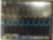
P1 shows the 2 signals at max offset. At this point turning pot more does nothing at limit of TIP741. System is in sync and Lock light is on.
P2 show shows the same set thing only I switched to 3x range on K21 so I am a factor of 10 lower at 378.8hz. I did for a reason, when I was check what range I wanted to watch on scope I had lower offset.
When I was nearing max offset, I saw the analog signal move up slightly to look like P1. What is happening show better using the 3x range.
Turns out it was not in complete sync until at max value. By chance this is the condition that Ronnie says you should have.
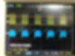
P3 Is the system in 3x setting with gain turned down and you can see the ramp in the Blue channel. I turned offset down far enough to make it apparent.
As you turn gain us this ramp flattens until it looks like P2. You can also see this in 4x setting at 3.788hkz when you look at whole gate pulse but it not as apparent. Not sure I would have caught this if I had not seen blue signal jump up slightly.
P4 I kept lowering offset until I saw the digital signal started to deform. That starts here at about Vamp = 1.71v so I captured the signals. You can see the deformed signal better in P5.
P5 is the lowest you can set the offset. Turning pot does not more at this point Vamp approx. 1.09v.
P6 is lowest offset setting but zoomed to show signals at 378.8hz
P7 is lowest offset at 3.8khz zoomed to show single gate pulse. You can see the ramp up that disappears at max offset.
I can see why Stan only can select either the digital or analog signals test points. You need the digital to set the offset and watch frequency.
You need the analog to set the minimum gain value.
I turned it up until all the digital pulses where full. I think I showed this happening in posts above.
P1 3.788khz max offset
Stanley A Meyer
P2 378.8hz max offset
Stanley A Meyer

P3 378hz 7.1v Stanley A Meyer

P4 378hz 1.71v
Stanley A Meyer
P5 Lowest offset 378khz
Stanley A Meyer
P6 Lowest Offset 378.8hz zoom in Stanley A Meyer
P7 Lowest Offset 3.84khz zoomed out Stanley A Meyer

How to VIC Transformer "tune"
VIC "tune" Formula:
Rsec. = (Rc1 + Rc2) / 2
How to connect VIC Coils:
https://drive.google.com/file/d/1Xbs6VF3d9O5G4vqxopcSih8Qu_cS50fg/view
My Circuit diagram:
https://drive.google.com/file/d/1xHysBjCCzZZwcgBttnJXzskK8IxNFYbL/view
Front panel:
https://drive.google.com/file/d/1ELezsvo2zTT0By4V3lqGxhrB2F18vyEC/view
Secondary coil - 1500 turns, C1 about 1930 turns, C2 -1000 turns. Too close to the "tune" point. At 1500 turns, the Frequency is too High! You must use about 3x9000 turns, and tune as is showed!
https://drive.google.com/file/d/1HDdS5mm9LvSzgiDmsoFPZWwRHE-CxhcX/view
The Full Waveform shape (not "tuned") - "fc" vs. "fc/2"
https://drive.google.com/file/d/1dQ14kHAI2_zIgNK33oGeSGM5smvWYfEc/view
Resonant bridge explain:
https://drive.google.com/file/d/18D2fuE8X5Y772g8F3iy-vrz8rXM3tQch/view
Important! Note, that the two Resonant Inductors are placed at common Ferrite core with the Secondary coil! They work "both" - like Resonant Inductors and like Secondary coils !!!
Tri-coil configuration:
Memo WFC 425:
"The resultant tri-coil configuration (Inductance core 53 - choke coils 56/62 - primary coil 26 - secondary coil 52), now, allows magnetic field coupling (71a xxx 71n) to pass through both resonant-coils (56/62) and secondary coil (52) simultaneously when primary coil (26) is pulsed energized by way of incoming pulse-train (46a xxx 46n). In doing so, magnetic flux-lines (71a xxx 7In) are induced into spiral-wrap coils (505a xxx 505n) to produce inductance coupling (511a xxx 51 In) between each secondary spiral-coils (505a xxx 505n) which are parallel formed to expanding magnetic flux-lines (71a xxx 71n) ... producing step up voltage potential of positive."
Here is why the Resonance bridge needs to be balanced:
Memo WFC 427:
"By doing so, Balance Phasing of opposite voltage intensity (+Vpp / - Vpp) is accomplished without experiencing current influxing caused by differential variances where Negative Voltage Peak Potential (-Vpp) is less than Positive Voltage Peak Potential (+Vpp) or Vise Versa ... allowing Inductor Resonant Choke Coils Electromagnetic Fields Intensity (+Z2 / -Z3) to be, in turn, free of Electromagnetic variances of intensity (Z2 - Z3). This non-voltage shift (Balance Phasing of opposite Voltage Potential) helps prevents atom displacement during "Snapping-Action" by which "Resonant Electrical Stress" of opposite electrical polarity (RU/RU' - ST/ST') is applied equally across Water Molecule (s) (85) to propagate either Static (585) or Dynamic (612) Electrical Charging Effect."
Stanley Meyer`s Memo WFC 420-421-422DA-423DA-424-425-426-427-428-429-430 (Copy Unlocked):
https://drive.google.com/file/d/1D33NqNY1AZEdQnu6IrTfFavwPIIRP3qV/view
Stephen Meyer`s Patent US 2005/0246059 A1:
https://patents.google.com/patent/US20050246059
Andrija Puharich`s Patent US4394230A:
https://patents.google.com/patent/US4394230
Stanley Meyer's Patent US4936961A:
https://patents.google.com/patent/US4936961
Stanley Meyer's Patent WO 92/07861:
http://www.rexresearch.com/meyerhy/wo92.htm
Stanley Meyer's Patent US5149407A:
https://patents.google.com/patent/US5149407A/en


Stanley A Meyer Vic Replications
Remember to share so people learn