
GO Faster Go Further
Established since 2001

Hydrogen Hot Rodding™ ©

Secure Supplies Group


Vic Bobbin Style 1 Stanley Meyer


Winding the VIC
all the VIC s are based on the same concept.frequency switch to transformer transformer, to inductors, to cell


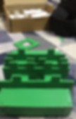


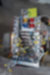
Brads Example of a Quality Build
Using Radio Am Ferrite Rods with close Al values,
Brad designed and 3d printed the corners and joiners with adjusters and some very cool secy looking bobbins to handle the High volt DC Getting back to Stan's Vic, can everyone see how the gap between the cores controls the coupling from the Primary to the Secondary which in return controls and fine tunes the voltage in the secondary and L1.
And if you follow through with this to the positive plate, it also fine tunes the charge on that plate. It would be easy to create a gap with setup by using two shorter rods on sides with coils instead of one long rod.
-New drive circuit provides a variety of functions and adjustments
-Ryobi 18V battery + programmable power supply makes setup more portable
-VIC made from Mn-Zn 10mmx100mm ferrite rods provides more accurate inductance's with similar
turns and resistance values as Stan's original VIC These cores have a lower AL value than all the
others I've tried plus a much larger winding window.
So, these cores give me much closer inductance values
for the same amount of turns and resistance than Stan had in his VIC.
Mostly what I'm trying to find is an off the shelf core that will give me the right balance. What I have found is that most off the shelf ferrite cores have AL values that are much too high, honestly I'd be surprised if any of them worked.
So far I think the rods (or the flat bar your using) have the best chance of working.
The problem I Had -You can gap any core and get the right inductance values, but the gap creates an invisible inductance and if it's too high it will take all the voltage.
I posted a video on this a while back on how the leakage inductance is so high my tests showed I needed a load impedance of greater than 1M ohm just to get the voltage from the turns ratio across the load.
Where did you got this core?
What is your AL value?
I contacted a supplier and said what range of frequencies i will use and they replied "we sugest about 2500 perm."
If you dont know and you have a LCR meter, you wind 100 turns or so, and measure the inductance with the mounted core, the go to:
http://powermagnetics.co.uk/calculator
enter inductance and number of turns you winded and you get the AL value.
High AL value core saturates at low freqs.
Try a different core like old color tube TV flyback core like Max miller did. I got some bubbles with tap water with this type of core.
I hope it helps a bit.The core has a permeability of 2000.
I don't have a LCR meter, but i do have an inductance meter and capacitor meter.
The fun thing is, that i see lots of nice waveforms on my scope.
It doesn't matter which coil i use a secondary or chokes

Vic Winding for 11 clell tubes
VIC:- primary - 200 turns / 24 gauge- secondary - 600 turns / 36 gauge- resonant chokes - 2 x 100 turns / 24 gauge
(in accordance with Stan Meyer`s US Patent 4,936,961)
MAx Millers Forum
The primary is a single coil 500 or 600 turns of 30ga
secondary is around 3000 turns 30 ga
c1 is around 3000 turns of 30 ga
c2 is around 2800 turns of 30ga
all in the same direction in relation to the core shape the feedback was center tapped......looks to be
NOtes
the transformers stan made were 29GA and 36Ga secondaries.
it depends on what you wish to try.
i would suggest trying exactly what stan made. the square vic was all 29 GA 29-30GA
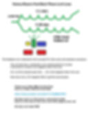
The VIC Coils
-
Transformer Primary Yellow
-
Transformer Seconday Blue
-
Chokes Red
-
Pick Up Feed Back Green


WIRE
29AWG Heavy Polyimide 240C rated, 29 AWG, .0113"


CORES

We don't have the AL value of the cores we are using but here are
some calculations
Original STAN
flat are 2000 perm
custom ordered,
Ronnie = Working Vic
Took some measurement, this is what i got.
88 turns one complete layer on bobbin 29awg .0113
65.87uh with no core material
4.811 mh with core material with no pressure on the core material at all just together
18.05 mh with core material with all the pressure i could put on them pressing them together
One thing is though is that we can change the variables around so it doesn't necessarily have to match stands as long as the inductance reactance is still correct
What I find interesting is how much change you can make in the inductance with pressure.
it's supper sensitive with that last bit of pressure.
I noticed that with the 10turn test.
AL VALUE
Looks like your around 230-450 AL. That's great. Very close to the original VIC core. Makes me wonder what the Ue was of the original cores so the type of ferrite could be figured out. I could do the math to figure out the Ue, then we could figure out the exact material of the original vic core, even though I don't think it's necessary. If you have the right material I don't think gapping the core would be necessary either, you could find resonance by changing the frequency, but it takes a different design. In that case I believe the PLL circuit will work. It's designing the coil that's hard, but I think we've got that down now:)
NON Original
Not working vic
UY1658 Cores this one is not original it is put here to get you understanding
i did a quick calculation here: http://powermagnetics.co.uk/calculator
i have 10 turns and 21.52uH
that's an AL value of 215.2 this is with 1/2 the core.
when i put the 2 together and make a 0 core its 3100 AL value.
so I'm guessing we calculate it as an open core.
as the gap changes the AL value... thoughts?
also that was with 32 AWG wire, on the bare core not on a bobbin...
with 28AWG its 116.3 AL value half core and closed core is 2600 AL
more calculations on the bobbin.
10 turns closed core is 3100AL and open is 135AL
wire wrapped close to the bobbin end with the core.
calculations on the AL value. They will help us a great deal.
Looks like the AL with the core gapped is pretty close to the 5 coil vic by Stan.
Just remember as you increase the gap you are also changing the coupling between the coils.
Russ, I think you were off by one number in your calculations above
AL=L(in nH)/ #turns, then take the sqrt of that number
18mH=18,000,000 nH
18,000,000/88=204,505
Sqrt 204,505=452AL
3D Printing Bobbins
3d Printing has now allow bobbins to be printed in every home with a pc and 3d printer.
I'm using decimal measurements in Sketchup and modified the dimensions a bit using the total length of the 6-in-1 coil bobbin rounded to tenths to be:
.3 + .1 + 1.3 + .1 + .4 + .1 + 1.3 + .1 + .3 = 4"
Both bobbins of the 6-in-1 are in four pieces; see the attachments including the zipped Sketchup sketch.
Also for the record, Dynodon stated the gauge and decimal representation of the magnet wire used was 29 AWG and 0.0155 inches.
The actual diameter of 29 AWG wire is 0.0113 inches according to this source:
http://www.bulkwire.com/wiregauge.asp
In the sketch notebook, it notes all the wires are 0.0115 inches in diameter which is approximately 29 AWG.
0.0155 and not 0.0115 inches should be a typo.
gave your sketch a whirl on the RepRap. It's looking very promising. :D I converted the Sketchup file to millimeters and exported it to .STL format attached below. I recommend printing with the support set to 'everywhere'. I tried it with no support and had sagging
I just finished revision 2 of this sketch and added the end piece for the bobbins; see attachments. A minor adjustment to the core ceiling of the bobbin was lowered a bit to reflect the core dimensions of 0.5"W x 0.125"H.
Nothing special had to be done to convert the sketch to millimeters? You simply had to go in Sketchup:
Window -> Model Info -> Units -> Format: Decimal | Millimeters
I found out that I needed to rotate the objects in Google Sketchup. I tried a print with it rotated and it worked much better with the raft. There was a trade off though, the "wings" on the bobbin didn't start off great. Printing with out the raft would be the ideal way to do it. I added some little indentations to the bobbin walls. They are only 0.5 mm deep, and they strengthen the walls, by "glueing" each side together. My test print only had 2 indentations, and I found adding a 3rd would be better. They shouldn't affect how the coils are wound.
I also extended the supports outside of the bobbin. I was having spots where the nozzle wasn't feeding material at the starts of the lines. That will give it time to get flowing again.
Sketchup and STL files are attatched.


WINDING
Ulf told me that each coil was later checked and tuned by hand also...how, he is not sure but with LRC meters and such... yes..everything was matched one part at a time... This he remembers,
Coil Winder Machine Page Here


.jpg)


Aluminium Case
The aluminium case helps stop coupling to the desk or plastic surfaces , and other things, it also can help increase capacitance, and stop health effect of emf.

Testing Measurement
Ulf told me that each coil was later checked and tuned by hand also...how, he is not sure but with LRC meters and such... yes..everything was matched one part at a time... This he remembers,
Coil Testing Page Coming Here Soon


Resistor 220 ohm code 411 9037.
Resister is 220 to 250 ohms by the way, at 50hz presents low impedance, at 5khz it presents impedance in mega ohms. Fuel cell presents impedance at 5khz in mega ohms, in series with L2 the fuel cell presents an impedance match. When impedance match occurs, L2 is happy to communicate with the fuel cell. No impedance match - no communication. Dc bias builds up on cell because of diode won't allow the pendulum to swing in tank circuit. Hope everyone is beginning to understand.
edit below chokes cw and secondary & primary ccw

30 ga wire for the bobbins on the C coresdon made a small error , he said 29 ga, 29 ga is not correct to fill the bobbin as the picture shows. 30 ga must be correct


Understanding the combined capacitence
resistance and choking methods
Once I figured out I need to add more turns to primary to get 10.5 ohms of resistance I became worried about turns ratio.
The process looked right is excel spread sheet above I did not trust the turns ratios was correct, s
Ronnie
Winding data shows I need a ratio of 5.567 to 1. Will not know if I get close enough until I actually wind the wire. I plan to start out with primary winding know length of wire that is equal to 10.5 ohms.
Coil winder will then give me number of turns for this resistance. Will do the same for secondary to see how close I get turns ratio. There were comments about being something than you have to play with to get correct.
Given a fix resistance and fixed turns ratio only thing in this system I can see you can change is spool width. I expect the changing the secondary would have the most effect do to increased length of each turn as you add more wire.
There is some discussion about this issue in the thread.
In this post he also explains coil relation to secondary and goal of getting voltage potential across coil plates.
: "Understanding How Stan Meyers Fuel Cell Works"
Using Stan's Vic and the numbers Don gave us as an example,
I will attempt to show how to impedance match it all.
Question is what is the purpose of Impedance matching?
The answer is Watts in must equal Watts out. (Isn't that right Mr. Watts: clap:)
Let's start with the Primary, I have already show it has 10 ohms
of impedance in it and how it is calculated.
Line(Primary) side=10 ohms
12volts/10ohms=1.2amps
1.2amps*12volts=14.4watts
Next we use a transformer (Amplifier) to match the Load side.
we need to know the total resistance of the load side.
Secondary side= 72.4+76.7+70.1+Re78.54+11.5=310 ohms
Now that we have a total resistance of the line side of 10ohms
and a total resistance of the load side of 310ohms
Next we take the 310ohms and 10ohms and use this formula to get the turn ratio.
Ns/Np=sqrt Zs/Zp sqrt (310/10)=5.567
So we need a turn ratio of 5.567 to 1
We know our line voltage is 12volts We can times this by the turn ratio
of 5.567 which is =66.816 Load Voltage
Now we have our load voltage.
Next we calculate the load watts
using formula (66.816 ^2)/310ohms= 14.4 watts
That's how you do it. :bliss:
Matt, The 11.5 is the feedback coil.....and yes that is correct the chokes must match the secondary....That's why if you take turns off the L2 they must be added back to L1. In Stan's example secondary is 73ohms close enough,
then 76ohm for the L1 and 70 for L2 if you take 3ohms off the L1 and put that 3 ohms back on the L2 you can see they all match to 73ohms.
Why does he do this? It's to get the slight potential difference in voltage needed on the chokes. Yea My brain can't keep all this straight, that's the reason for the spreadsheet. Too much math to deal with all at the same time. Now you can see when someone ask me a question, how my brain gets all scrambled.
End Thread Comment
=============================================
Before doing anything else I decided to see what my systems would look like with 29 gage wire. I used the information from the primary coil I wound to estimate the ohms per turn and came up 0.0156omhs/ft. (Coil I wound was 8.4 ohms and 540 turns so I divided 8.4/540 to get this estimate). I then used this number to estimate the number of turns required to get the required ohms for each coil. Finally, I added all the secondary side turns include the one for Re and divided it my primary turns and got 29.45143.
This is close to 30 a 30:1 ratio. I am not sure if this is correct but none of the other ratios seemed correct. I include Re even though there is not a coil for it as Re ohm value was include by Ronnie in doing his calculations and it did not seem right to leave it out. I do know there will be some changes in value as length of turn on larger coils will be slightly longer which should reduce number of turns required to reach desired ohm value.
Table below is from my excel sheet I used repeat Ronnie’s calculations. I find do the calculations myself helps me understand where numbers come from and why. Again, the turns work at this point is an estimate to see if I was even in the right ball part.
As the above table gave close to a 1:30 ratio I will continue winding coils to see what results I actually get. As I want to get keep the ohm values close to numbers above, I am planning on winding the number of feet of wire that should give me desired ohm value. This means I will need a method to accurately determine desire length of each coil.
To do this I build a jig that I can wind wire on. It will be two spools 5 feet apart mounted on a board, so each wrap is 10 feet long. Using spools this far apart I should be easily able to fit the longest length.
Note: There was some discussion in the thread about dealing with turns ratio and resistance mainly that one effects the other. Discussion did not say which is more important other than Ronnie’s comment to not mess with turns ratio. See his discussion on keeping Secondary, C1 and C2 ohms around 73 ohms and taking turns off C2 and putting them on to keep total ohm value of those two coils at average of 73 ohms. i.e. for each turn taken off C2 one needs to be put back on C1. Which means you need to have enough wire available to do that.
It was recommended that you leave wire on C1 and C2 long enough to adjust the balance which means you should have some length of wire that is not on the coils. This means you will have some wire and ohms that are not in turns calculation. Extra wire resistance is this there until satisfied with balance, but it will not be in magnetic field, so I am not sure how to account for this.
At this point I still do not have cells, just trying to understand why this piece is the way it is and if I can build it correctly even though I understand adjustment of C1 and C2 require properly configured cells. Ronnie even states you need to start with cells and build to them not the other way around as they define load you trying to balance.
I have rewound about 70 feet of wire that I took off the primary coil on to the Feedback coil as I calculated half of 11.5 was slightly over 70 feet. Turned out to be slight less than 70 feet to give 5.75 ohms (measured). Once I add the center tap for the 5-volt offset I will add another 70 feet. Turns actual wire resistance is slightly high that estimated reference number I was using.
I wound it this way a that is what circuit diagram shows. I think I read others have wound both wire at the same time. I have been trying to figure out which is the correct way and it may not matter the way it is connect to K14. Voltage difference is not issue as it phasing of the signal is what is being used.
.png)

Stans VIC finally reverse engineered and ready to build.
What is the Total Z of this circuit using Stan's formulas?
You can work out the Z value of the L1 and L2 along with the capacitance value from the chart below and the formulas from the Tech Brief Eq 1,8,9.
This will be with air core values.
I would like to see everyone's answer; this could show how everyone has a different answer.
Also notice where the #(10) shows up.
Only thing I see 10 of is the ohms for the cells.
(could Re be a factor of 10??)
Also I find it interesting that I appears many people do not seem to build the feedback coil even though Ronnie uses the Z value in all his calculations including the turns calculations.
The 10-11 cell is not made to be adjustable.
It is made to be stable, Meaning, every cell machined to the same size so each and everyone will have the same capacitance.
Like max said that is the reason their is one cell that is not hooked up.
That is how you adjust the capacitance, by hooking up one through what ever to get the capacitance you need.
As in the video you can see by adding more capacitance you can reduce your inductance. If you are using a varic to drive your cells then you know your drive frequency is 120Hz once it goes through the bridge rect.
Then you need a resonate frequency for the inductor and capacitors that will match your drive frequency. The permeability of the core is something we all have been playing with. My best luck so far is some were around 2000 perm.
The higher perm. the less winds you need which will give you the same inductance as a low per. with more turns if you follow me. Right now I am useing a low perm on the primary and a high perm on my chokes. It is working out well for me right now.
You will have to experiment with your setup. That is way it is so critical that everyone have the same setup. Because what works for my setup want work on yours.
NOTE FROM TONY WOODSIDE
Well as Stan states in his papers that the chokes act as a frequency doubler, then you cannot use the basic series LC formula 1/(2pi* sqrt(LC)) to find the Resonant Frequency. So i came up with a formula to find this resonant frequency.
Here is an example:if you pulse the Primary @ 5khz, the Secondary will also pulse @ 5khz, the chokes will have 5khz going in but will have 10khz coming out so that the Capacitor will be hit with a 10khz frequency!!!
So for a normal LC non-doubling circuit you would have the following:Primary pulsed @ 5khz the LC resonant frequency for a setup with the Sec+L1+L2= 9H and C= 1.6nF Resonant Freq. = 1327 HzNow this same set up as a LC Frequency Doubling circuit would give the following resonant frequency:
Primary pulsed @ 5khz the Resonant Frequency = 938 HzSo as you can see we have a lower Resonant Frequency from the same circuit and the only difference one is configured as a frequency doubler. This has to be accounted for in Stan's setup!!!!
Note Petlov says
we can also note we can also achieve some versions by having a bifilar choke assebly after and between vic toriod ( primary secondary chokes) assembly and cell
Woodside note
and we can also have a multi tap mechanial voltage doubling trigger voltahe step charge see modern circuits..
NOTE FROM DON
The blocking diode goes to the positive choke and always goes to the positive tube (outside tube).The negative isolated ground wasn't hooked to any ground either.In Stans circuit,there is a 5 amp 1000 volt diode between the TIP120 and the primary coil.
Stan also put a diode across the inputs to the primary.From ground to positive.
NOte From MAx
ordered Magnet Wire 30 AWG Gauge Enameled Copper 200C 5lb 15660ft Magnetic Coil Winding
you can look at the ohm reading of dons measurements, then look up the ohms per 1000ft of wire. a little math will tell you how many feet is on the bobbin. i posted how many turns i came up with somewhere..
ohms value can change slightly, due to exact size of wire and tension stretching it. the wire size can vary slightly due to tolerance and manufacturer.
the coating on the wire can change the inductance sllghtly, thickness vary as i said about the wire
from memery, 500 turns on primary, 3000 secondary, inductors are 3000 and one was 2800..........roughly
i will find my measurements just remember different wire from different companies can vary in ohms and even you put too much tension on it can change the readings.
i took and wound the wire to read the same ohms, then took note of everything else.I believe the turn count will be greatly effected by this. more then 10 turns. I am in favor of 500 turns to the primary and 3000 turns for the secondary.... inductors changed respectively.
3000 turns is a lot, the inductance will change greatly with the turn count. and odd number of turns effect things greatly as well
I hold to my theory that 2000 perm it is for the inductors
and my theory is the primary and secondary needs to be an even number, based on transformer theory. however there is no known theory for the inductors. I say theory because there is no car running on water at this time. when we are finished and the car is running, we call call each theory a fact.
all electric theory are called theory because , new theory comes along all the time. and science simply can not explain everythingtalked to don last night on the phone.............he says 29 gage is what he measured.
however different manufactures make a minor difference in wire size. i still like the 30 ga
i wound 29 and 30............30 ga looked the best
Vic 1 Ferrite Core
Backup and yes we have 4 to 5 backups you should immediately do same download it now be warned
Different perm of ferrite cores tested with a ramping wave pulse output HIgher Perm Higher Voltage
Custom Cores

Note =VIC made from Mn-Zn 10mmx100mm ferrite rods provides more accurate inductance's with similar
Sourced Ebay category link here
These cores have a lower AL value than all the others I've tried plus a much larger winding window. So, these cores give me much closer inductance values for the same amount of turns and resistance than Stan had in his VIC.
Backup and yes we have 4 to 5 backups you should immediately do same download it now be warned
Dan thanks for posting this. These look like the rods I purchased just longer. I was not sure how I was going to build mounts for these reason I decided to start with flat pieces. He says he is not using gap. It is my understanding that gap serves 2 purposes 1) lowers AL value and 2) is used to do coarse adjustment of the phase offset of signal. Ronny Walker talked about that in his thread comment about gap by him for example
Re: "Understanding How Stan Meyers Fuel Cell Works"
« Reply #606, on November 11th, 2016, 11:33 AM »Last edited on November 11th, 2016, 11:35 AM
Getting back to Stan's Vic, can everyone see how the gap between the cores controls the coupling from the Primary to the Secondary which in return controls and fine tunes the voltage in the secondary and L1. And if you follow through with this to the positive plate, it also fine tunes the charge on that plate.
It would be easy to create a gap with setup by using two shorter rods on sides with coils instead of one long rod.
I am BradK on youtube, I made that video Dan posted. I have been doing tests with and without gaps in the cores. Mostly what I'm trying to find is an off the shelf core that will give me the right balance. What I have found is that most off the shelf ferrite cores have AL values that are much too high, honestly I'd be surprised if any of them worked. So far I think the rods (or the flat bar your using) have the best chance of working.
The problem I'm having-You can gap any core and get the right inductance values, but the gap creates an invisible inductance and if it's too high it will take all the voltage. I posted a video on this a while back on how the leakage inductance is so high my tests showed I needed a load impedance of greater than 1M ohm just to get the voltage from the turns ratio across the load. I thought by getting current flowing the gas bubbles at electrodes would restrict current enough to allow the process to begin but my research since then says otherwise.
Also- Do you have a 3D printer?
I bought one last August for $123 with shipping. Definitely worth it. After fixing a few problems on it it's worked great ever since. I use Tinkercad (free online 3d modeling program) to design my bobbins etc. A 3D printer is the most useful thing I have bought for SM research so far.
Vic Core Options that work
Stans Original Compared


Vic 1 PLastic Bobbin
3d Printer Files Section

Earls Build
Continued work on ferrite core holders building the coil sides. I cut the plexiglass to close to the correct size and squared them up and ground them down to desired size with disk sander. While I used a power mitre saw to do ruff sizing you need to be very careful when working with plexiglass or anything this small. The coping saw I used to cut on hole actually would do this job.
The Cutting out hole.JPG shows the four counter holes you need to turn the coping saw. Done on my drill press. I set the back distance then just move plate to dill the holes it was quick. The box lines are the size of the tubes. I used them to locate the drill hole and then cut inside line with coping saw. I then filed hole down to fit tube. This ensured that hole was a tight fit.
The Drill hole for saw blade.JPG show larger hole being drill needed to get coping saw blade into plate.
Cutting out hole.JPG show hole being cut out with coping saw. This was the first plate I did once this one was finished; I drilled all the plates then took vise off drill press as it was easier to saw the hole with vise clamped to table. I used first plate as guide to file down hole in remaining plates when it got close used tube to check hole so I got a very snug fit.
Side tube with coil sides.JPG show on of the side tubes with coil sides installed. With the snug fit I used gel super glue to glue plates to tube. That gave me enough working time install the plates and get them square.
Next step is to finish coil winder that will hold the tubes while wind the coils.


Proven Working Alternative

Backup and yes we have 4 to 5 backups you should immediately do same download it now be warned
Note from Brad
Simplifying the VIC circuit and doing the math to see what it shows us. We know the VIC is a step up transformer, and as such it has to draw the same (close to the same) amount of power on both the primary and secondary sides of the circuit in order to work properly. First problem, how do we calculate the turns ratio when we only have the resistance, wire size, and bobbin dimensions of each coil?
Second, if all three coils (secondary, L1 choke, and L2 choke) are on the same core does each coil act as a secondary coil? Third, if both the secondary and primary coils used the same size wire and their bobbins had the same dimensions can we use the resistive values of each to determine the turns ratio?
Following the math shows us a little bit more about how the VIC works. It shows us that the secondary coil is the only coil in the secondary circuit has an induced voltage, and that the chokes only act as chokes-not additional secondary coils. It shows us that the turns ratio is about 1:4.56 and that peak current through the secondary coil is about 250mA. Also, the spreadsheet shows a maximum secondary current of 255mA required to produce 20kV across the load at 10kHz.
*Keep in mind we are assuming a pulsed DC signal with a pulse long enough to get full current flowing through the primary and secondary circuits. In reality it is difficult to get high currents flowing through the circuit because the rate of rise of the current is limited by the L/R time constants of the circuit. In all my testing the only thing that has caused the circuit to pull more current is when I increased the duty cycle of the resonant and gate pulses and added lower amplitude pulsing during the gate time.
the
the vic transformer
1200 perm is right on the money
1600 perm is on the money with a piece of tape on one side to make a gap.
2000 perm however is closer to the frequency of 5khz
i would say the inductor needs to be 1 H for 10 cells in series
really i am not sure of the inductance needed for one cell
i have tried the isolated ground to ground.....as well as grounded the neg of the cell......... nothing
as long as the amperage is low..........should be no harm done in the connection
the injector would have been grounded to the engine block
Feed Back Coil -Pick Up Coil
Used to Find and Lock Resonance The pickup coil is used for resonate feedback to the scanning and PLL circuit that senses resonance. More or less senses the highest peek voltages and locks onto that frequency.They will be no amp draw from your power source at resonance the transistor will run cold not even warm. This plainly states no amp flow in the cell. Nothing but voltage.
Well according to Don's drawing the center tap is start of the wind and logically you would want a very small signal going to the phase lock loop circuitry.
Thereby giving you small deviations on the 5K hertz center frequency. If you read the international patent Stan talks about impurities knocking the cavity out of resonance. Impurities which would change the dielectric value of the water molecule. See attached photo for clarification.
Again none of this would have been possible if it weren't for Don Gable documentation of the Stanley Meyer Estate. See Don's attached drawing for clarification.
so 2 coils center tap is the startsss which one is longer then the connected side or the not connected side The one that gives you the most bubbles using 10 Vic's
need to figure out 10 center tap non-inductive feedback coil need to be tuned in.

This shows the amp draw from your battery or power supply at resonance. He states at startup the amp draw will be 25 m/amp and at resonance it will be 1-2 m/amp. So if your drawing more than 25 m/amp at startup would you not think you have something not designed properly on the primary side? I would think so. the chokes are part of the turn ratio of the secondary. Which means that the secondary turn and the choke turn are all added together for the ratio on the secondary side of the transformer. What he left out was the word (and) in between secondary charging chokes.


I agree with that but and measures taken from cell ,what says that on primary winding may be different input
and according to my knowledge it is easier to tune cells with stronger power -Of course that can slowly reduce
and pickup coil if so then it does not allow drop of magnetic field or opposite
and as we see in the transformer secondary coil and cokes it's all one secondary coil which is located only 50% in unipolar magnetic fields
and so we have a potential difference plus and minus properly distributed 50% 50% in both fields
and as you said that is a common transformer
what most people is missing is how to get more voltage than 12volts out of the primary when it collapses into the secondary. A typical 1-30 stepup transformer ratio with 12volt into the primary will give 360 output voltage. Everyone needs to look into how to get the 12volt to produce a couple thousand volts or more before it collapses into the secondary. There is a way to do this, and it all depends how the primary circuit is build and designed. Study how a fly-back transformer works and you will find the answer.
The 25 milliamps is measured going into the cell, not into the primary. The primary input current will be much higher. That being said, it still boils down to watts in watts out. So if we put 12 volts in and 2 amps, we get 24 watts power in. Now if we have 25 milliamps at the cell input, that means we have 960 volts going to the cell, still 24 watts. Then when resonance is achieved, at 2 milliamps that would be @ 12kv at the cell, again still 24 watts. Watts in watts out.
The way I am reading it is this: You are pulsing in say 360 volts to the capacitor, which the diode (600v) can handle easily.
This voltage can't return due to the diode. So in goes another pulse and we have 720v stored in the capacitor, then on the 3rd pulse its
1080v etc. I just think the the huge voltages are accomplished inside the capacitor (cell) and not in the vic coil. When the capacitor reaches
the required voltage (matching the dielectric of the water) the water breaks down.
The cell is after all an unlimited capacitor only limited by the water itself. And when that limit is reached hey presto!
I have no idea how to measure the voltage potential in between the plates but that's where I think you will find the high voltages and not
in the vic coil.
resonance should start with less impulse and more watts or power in creating HHO gas,and then move slowly with increasing pulse and decreasing power -Now if you hit a high voltage from the start such current will pass through the water without any problems
when we create HHO My opinion is ,bond breaking is also liberates current and this current will increase with time in cells-not chokes
the purpose of chokes are to limit amps. however, clearly stan called them charging chokes and speaks of a charge pump. a cell is not a charge pump. the inductors are the charge pump.....resonant charge pump...... the cell then receives that charge
the only way to do that is to charge the transformer, which is how i get the step charge on the scope.
the chokes are on the same core as the transformer, so they are charged when the transformer is charged
the only way to see it, is to do it.......you need the setup of meyer, or simular
amps are current, which is electron flow. volts are independent from amps. if you were only using voltage potential.............electron flow would be at a minimum. a voltage potential, would not be consuming anything. like a battery not connected. it has pos and neg ions...........a voltage potential. you can charge that battery with ma. or huge amps. you can hit it with high voltage pulses as well. over charge the battery, and you produce hydrogen
not going to get into how to create more voltage on the primary side with 12volts there are more parts on the primary side than just a frequency generator and a transistor. I gave everyone a reference to look into, there is a lot of math involved on the primary side. Either you believe in Stan's words or you don't. He said no electron flow on the secondary side just voltage other than 1-2 m/amps through the cell.
Stan said no electron flow on the secondary side just voltage other than 1-2 m/amps through the CELL MAIN ROLE OF Stans transformer Preventing the flow of electrons AND PHYSICAL thin wire would not withstand FLOW
But if you fill CELLS with an electrons Magnetic field OF transformer AND HIGH ELECTRICITY WILL PREVENT ENTRY larger amounts of electrons in the WIRES NOW STAY resonance AND magnetic field that pushes electrons FORWARD AND BACK Which are located only in cells
AND THIS IS WHAT WE ARE LOOKING For , WE NEED ONLY CONFIRMATION OF DATA
The reason I started this thread is so many people are using a frequency generator and a transistor to pulse 12volts or what ever voltage into a primary and expecting more voltage out of the secondary than the turn ratio will allow. Stan used an example of a 1-30 ratio transformer. If you put 12volts into that transformer all your ever going to get is 360volts out. Well If you believe in what Stan says, he said the voltages can reach as high as 20000volts. But if you find a way to turn the 12volts into 600volts first you will output 18000volts with a 1-30 ratio. Now the challenge for everyone is to find a way to do it. While maintaining your resonate frequency.
STANS TRANSFORMER IS ONLY DEVICE FOR resonance ,And as you have already proven YOU HAVE resonance in THE WATER cell or Capacitor
Now the resonance WILL resonate that charge in a cell FOREVER FOREVER FOREVER FOREVER FOREVER
AND BECAUSE OF magnetic fields AND CHOKES ELECTRICITY will not enter into TRANSFORMER Will remain in the cell where AND WILL NEED TO BE
Produce a higher voltage on the primary than 12volts using 12volts. ( look into the design of a fly-back transformer)
The chokes are part of the turn ratio of the secondary.
You can not just use a frequency generator and a transistor to pulse the transformer.
Phasing the transformer is critical to getting it to work.
And we can't put any more than 600 volts from secondary to the chokes/inductors.......
According to the upper limit of the inline diode.
Ok C can get up to 500v from a 120v to 12v turned around and pulsed.
So that's 384% more power than normal.
ok so vic coil is 500 primary and 3000 secondary. Ratio 1 to 6.
So if we put 12v in we would expect 72 volts out.
But working on the pulsed theory we might see 277v or thereabouts.
So if we double the input voltage to 24v the figure comes out at 554v
Now that's magically just below the the diodes upper limit.
Once beyond the diode we still have a step up of 1 to 2 from primary to the inductors.
Oh goody that gives us 1108v as a straight ratio. Over the 1000v threshold.
But does the pulsing effect stop at the diode???? if not and we are looking at another gain of 384% twice........
Eh that gives us 2127v or 4254v if its twice.
So can I hazard a guess that we nee to be putting in 24v
the diode will pass the pulsing. so the chokes will charge as well
i got over 2k volts onetime with a transformer that was not connected
30gauge wire at 1000 feet has a resistance of 103.2 ohms.
Don Gabel gave us 2 readings 11.1 ohms and 11.5 ohms.
That comes out to 107.5 feet and 111.5 feet. Seeing that is a noninductive bifilar wind one would ask where does the voltage come from that feeds the phase lock loop circuitry. It would come from the no connection wire!


you need to figure out 10 center tap non-inductive feedback coil need to be tuned in.
Not just one !!!
""I had the VIC circuit system at my house twice.
The first time was without the GMS control panel.
I had to bypass parts of the systems to get the VIC cards to turn on.
Then once I had them working.
""I WAS ABLE TO GET THEM LOCKED ONTO RESONANCE.
But there was never any gas being produced.
""(this means that the pll and scaning circuits are on the vic card ,and read
on...''.....''the scanner would lock on to...''
When looking at the scope shots of the resonance signals,it looked a lot like what we all
have seen with our ouw setups.
The only difference was that the scanner would lock onto the third harmonic of the signal.
It never locked onto the first or primary one.
By this third harmonic I mean,it would lock onto a pulse train of three pulses.
The first pulse would be the largest,the second would a little smaller and the third
would be the smallest,and then it would keep repeating.
Now there may still have been something else that needed to be hooked up that I didn't
have .
Or there may have been something Stan had removed to keep it from working that we don't
know about ,because he never published it to prevent anyone from replicating it.
So that's about all I can say about it. I couldn't get it to work.
Too much of the system had to be put into a bypass mode,that may have kept it from
working,or something was still missing that we don't know about.
Don


Thinking like a radio wave all voltage a little bit of magnetic and absolutely no current!
MAx Miller Reported He got zero current and 300 volts across the cell mili ohm meter had no movement.........none
He is sure there was a mi-nute amount......the point is the feedback would be picking up a very small field
Testing the Original VICS
Used to Find and Lock Resonance
Don "Also was able to test all the VIC driver board and they would all lock on to a resonance once I adjusted the small blue pot on the board. It's a frequency centering pot. It sets up the range of the scan frequency. No gas output at all, it would make the same signal as my own test. An AC sine wave, at a couple hundred volts if my memory serves me right."
Heat Sink & Transistor
VIC


This shows what the signal should look like into and out of the Stan Meyer VIC.
quotes from stan meyer " to accomplish the formation of unipolar gated pulse-wave (64a xxx T3 xxx 64n) without experiencing "signal distortion" or "signal degradation" (preventing transformer ringing during signal propagation) as elevated voltage levels ""Switching Diode (55) of Figure (3-22) prevents Bidirectional electron flow (current flow in one direction only) since Blocking - Diode (55) only conducts "current flow" in the direction of schematic-arrow while being placed in-line with VIC Circuit impedance interaction (R1 + Z2 + Z3 .•. Re),
as mathematically extrapolated in Circuit Equation (Eq 9) ... Diode (55) being placed between Secondary Pickup Coil (52) and Resonant Charging Choke (56) to act as an electronic switch in open-position during pulse off-time (T2) of Figure (7-8) while preventing electron flow in reverse direction when Inductor (L1) collapsing electromagnetic field (FLl) produces another unipolar pulse wave-form ( 64a - 64b) ... producing unipolar voltage wave-form (64a xxx 64n) during repeated pulse-signal (46a xxx 46n) on-time (Tla xxx TIn) ..
. allowing the formation of an gated pulse- frequency pulse-train (64a/64b - T3 - 64a/64b) when pulse off-time (T3) is greater than time-period (T2) ... input-signal (49a xxx 49n) being a Pulse-Train where (T2) pulse offtime (T2) is adjusted to allows Unipolar Pulse-Train (64a xxx T3 xxx 64n) ... outputting Voltage-wave signal (64a xxx 64n) being a pulse-frequency doubler due to Inductance Reactance (FL) of Inductor Coil (56) of Figure (3-22) when collapsing magnetic field (FI) of Figure (7-3b) re-cuts coil-wrap (Ll) during each pulse off-time (T2) ..
. producing a second unipolar voltage wave-form (64b) during the rise and fall of magnetic field (71), as further illustrated in (620) of Figure (7-1).""Component Interaction promotes Component Reactance during D.C. pulsing operations while allowing variable voltage amplitude (Vo - Va -Vb - Vn) of Figure (7-13) to be attenuated independently of Voltage Pulse frequency""Inductance Reactance not only increases voltage across water-capacitor (ER) beyond applied Voltage Potential (626) of Figure (7-7) but, also, establishes "Impedance Field" (FL) across Inductors"" increases applied voltage amplitude (Vo - Vn),
doubles input frequency (64a * 64b) when 50% Duty Cycle Pulse (Tl = T2) is inputted, effectuates "Step Charging Effect" ""Inductors (LIIL2) should always be larger than Capacitor (ER) of Figure (7-2) in order to maximize amp restriction to enhance "Voltage Deflection" ""Capacitor (ER) should remain relatively small due to the dielectric value of water ""In terms of thermal explosive energy-yield (gtnt) under dynamic pressure of compression approximately 7.4 (µl) microliter of a liquid-volume of a water droplet per injection cycle is all that ~s required to run the Dune Buggy 1600cc 50hp VW I.C. engine at 65 m.p.h. on the open road; whereas, a typical 325 hp diesel I.C. truck-engine would require about 48.1 (µl) microliters of a water droplet per injection cycle to accomplish the same open road performance. (see WFC Water vs Gasoline Energy Content Equations (memo WFC 429)."
Vic Style 1 Core
VIC
Ferrite Core
The vic transformer Core Permability
1200 perm is right on the money
1600 perm is on the money with a piece of tape on one side to make a gap.
2000 perm however is closer to the frequency of 5khz
Inductor
i would say the inductor needs to be 1 H for 10 cells in series
Power Supply Frequency Generator
of the VIC CIRCUITS

Can anyone explain to me what the unipolar magnetic field coupling is exactly?

my theory is its a circular constant motion of energy
Not sure why Stan uses unipolar in the description, but the magnetic coupling is how a transformer works. A pulse is made in the primary coil when a voltage is applied. When that pulse ends, it is transferred through the core material as a magnetic flux, and picked up by the secondary coil. There isn't any physical connection between the two coils. So power is transferred through magnetic coupling. Only a pulse can passed through, it has to turn on and off to work. If you just apply a straight voltage to the primary , it won't pass through the core until it turns off.
They are time constants involve in pulsing the primary Di/Dt that is his the reason he shows 5 pulses for 5 time constants. Look into this you will find your answer.
yes ronnie knows i was messing around. you will not find any unipolar pulse in the test books............ it is the way the pulse is input into the coil and back out again.............there are many educated people who have said meyer was a scam, because there is no such thing as a unipolar pulse. but there are several on this forum that have generated them....not just Max
Home Builder Replications
VIC
VIC Driving Circuits
this is the driver for the vic in that board, it is there end also is a variable voltage driver
obviously we can see a voltage changer, and the pulse into the pnp transistor would be the inverse of the pulse into the npn transistor at the end

Amplitude Control from the VIC
"While working out the routing of the various circuits in the VIC card,I have found that there are four op amps on the one end of the board.
Three of these op amps are shown in the schematic,and the fourth one is not.The very first one of the op amps, the one closest to the tabs that plug the board in,is not in the schematic,and gets a signal from some source,and the second op amp gets a signal from the GMS control panel circuit Analog Voltage Generator.
Now these two signals come into the coil pack through the nine pin connector and pass into this board.What I have found is that the first two op amps are wired in parrallel and go into the third one.
There seems to be two different signals coming into these first two op amps,and are being joined. Ok so my question to you all is, what other signal could be coming into these op amps?
What purpose would it be to join two signals together through op
Those op amps go to the voltage amplitude control circuit.

Tesla Vs Meyers
Look Very Close at the Details.
This is really just a charge pump, it is Tesla 101, if you take out the spark gap And secondary side of a tesla coil schematic, this is What you get. The entire secondary builds over time, (provided You have a high insulative barrier between The secondary and the "outside world" once that is breached, Through an arc to the core, etc, you have reached your max. Notice how thick meyers insulation was between his coils and the core, How they were isolated etc.
Stan Meyer-VIC Replication parts
-4 ea pieces UY1658 MnZn ferrite core from Ebay, Amazon, Aliexpress
-4 ea pieces 1613-0 bobbins from cosmocorp
-3,000ft 29 AWG heavy magnet wire from Temco
-3/8 or 1/2 plastic washers
-MUR1560 diode -200 or 400 grit sandpaper
You'll also need a means to clamp the cores together, I mounted mine in an aluminum enclosure with aluminum L channel, screws,
and delrin bushings against the cores.
For the connections I used a terminal block as well as delrin bushings, insulated BNC connectors, and SMA coax connectors.
*The ferrite bead pickup coil will not give you accurate voltage readings... but it does show you what your waveform looks like and makes finding resonance much easier.

I'm a paragraph. Click here to add your own text and edit me. It's easy.

It is Crazy we have to have 3 and 4 and 5 back ups of sites docs and videos it is a constant effort to keep this here
save all that you see and re upload after all the only reason you can see this is we have done that consider supporting us
JOIN AS A SUPPORTER or Donate HERE https://www.patreon.com/securesupplies
PAYPAL LINK Donation https://www.paypal.me/SecureSupplyUSALLC/25
My Paypal daniel_donatelli@yahoo.com
MY BITCOIN ADDRESS: Bitcoin Donation
BCH
qzskj2v6sznjtwa8wpuyhse4hwh3e6lhrsg8qvtl56
BTC
1BiTfFLg4c3rtFzBHf3joHNki5yrjtZ4Gj
Contact me at email:
Books Can be Ordered here
https://danieldonatelli.wixsite.com/hydrogen-power-gas/company-books


Tunable Coil


Home Builders
Whilst I await tooling and material. I have completed some more theoretical work. Based on some of my research from others (Petkov) I have started to plan towards a VIC. I began also with the VIC measurements from the estate in Russ's posts on this site. I have created an image to help with construction and a calculator that can estimate turns to a desired mH value. I have used this many times in EQ design. It's close to within 10-20% normally.
In order to get accurate values, there are notes towards measurement steps to define Al value for the core in question. Variations can be +/- 25% and that does not account for the 'broken' core. Measurement is the only way. Working files attached.
Values in the xls currently are based on 3400nH core Al value taken from the data sheet (which is certainly not the case with a broken core).
I think it is important to specify things in this manner, as cores become unavailable having a target mH value (and Q) allows the process to be translated to other cores. At least, that is my preference.
Interestingly, the winds suggested by Petkov are equal for C1 and C2 whereas the original unit measurements show deviation here. This could be due to inconsistency in winding but should not be discounted.
C1: 76.28mH @ 6.27Q (1kHz open) C2: 64.26mH @ 5.79Q (1kHz open)
C1: 1218.8mH @ 69.5Q (1kHz on core open) C2: 1093mH @ 68.9Q (1kHz on core open)
A difference of around 10-15%
.png)

